Purchase price centrifugal pump + advantages and disadvantages
In this writing we will explain about 10 HP centrifugal pump flow rate and other specifications. Keep reading. The three-phase 10 HP horizontal centrifugal pump offers an optional input voltage range.
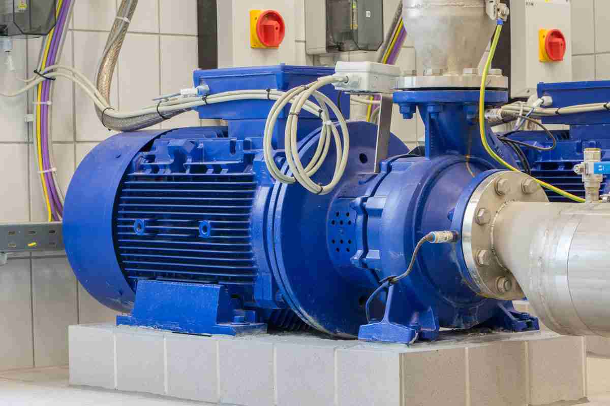
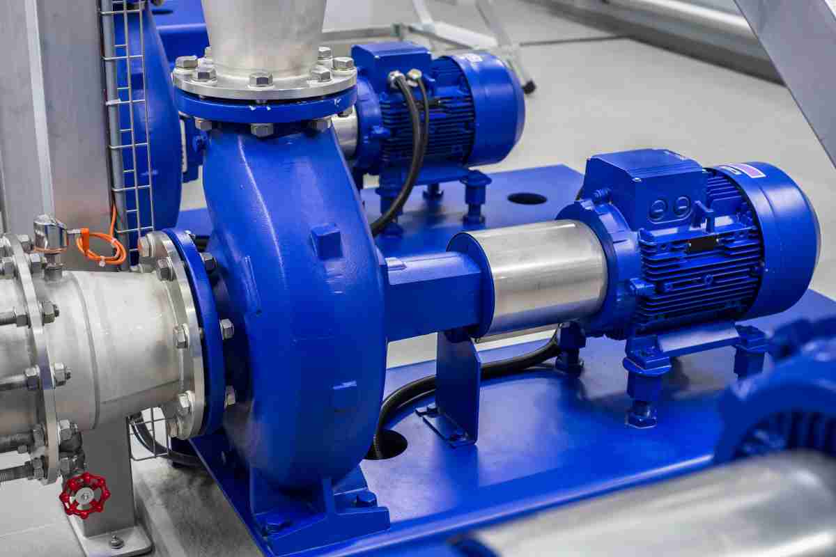
centrifugal pump parts
With the identical inlet and output diameters of 40mm (1-1/2 inches), the maximum head is 82m (269 ft). An inexpensive 10hp single suction centrifugal pump can be used to compress cold water for usage in air conditioners, refrigerators, bathrooms, etc.
10 HP horizontal centrifugal pump having an inlet and output diameter of 40 mm, a maximum flow rate of 8.3 m3/hour, and a maximum height of 82 m.
 Properties:
The horizontal structure of the centrifugal pump. The entrance and outflow both have the same diameter. It can be utilized outside if a protective cover is added.
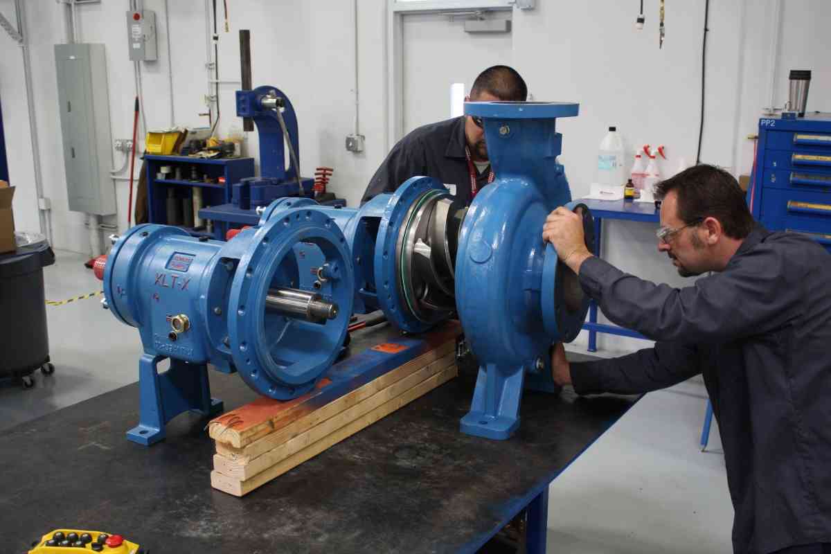
Installing and maintaining it are simple. You can merely remove the flat nut from the vertical pump connection without disassembling the piping system. The entire rotor can then be taken apart.
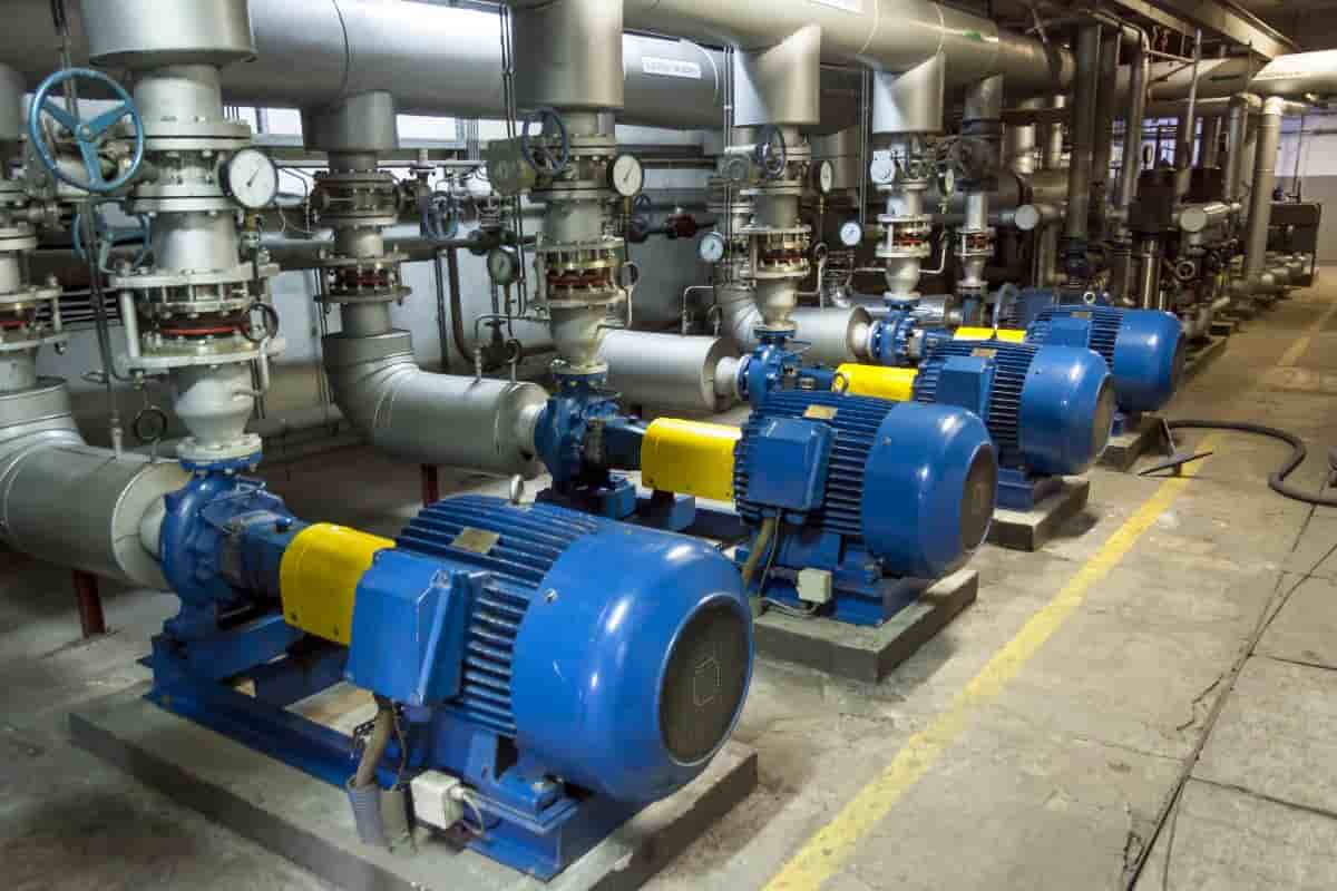
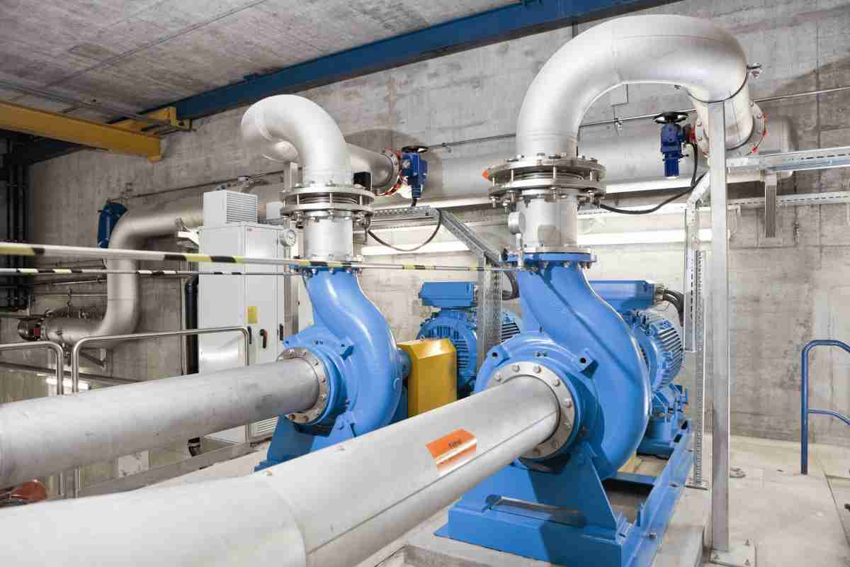
Depending on the flow and head requirements, the horizontal centrifugal pump can be operated in a series or parallel connection.
To accommodate various connection scenarios, the pump outlet installation angle can range from 0° to 180°.
Advice for troubleshooting an overheating centrifugal pump
Properties:
The horizontal structure of the centrifugal pump. The entrance and outflow both have the same diameter. It can be utilized outside if a protective cover is added.
Installing and maintaining it are simple. You can merely remove the flat nut from the vertical pump connection without disassembling the piping system. The entire rotor can then be taken apart.
Depending on the flow and head requirements, the horizontal centrifugal pump can be operated in a series or parallel connection.
To accommodate various connection scenarios, the pump outlet installation angle can range from 0° to 180°.
Advice for troubleshooting an overheating centrifugal pump
- A centrifugal pump check
Like a little horse pulling a big cart, the chosen force is incompatible. Long periods of time spent running the engine at full capacity raise engine temperature. When an engine has a short-term constant or intermittent operating system, it starts up far too frequently or operates continually.
The fixed quantity marked on the motor must be observed, the starting times must be restricted, and the thermal protection must be carefully chosen.
- Examine the engine
Improper wiring. The motor temperature increases quickly when Y and are connected incorrectly. Phase-to-phase shorts, short-circuit interruptions, and local grounding are issues in the stator winding.
The engine is pretty hot in some spots but not seriously. In a dire circumstance, the insulation burns. The cage rotor is broken or detached.
The iron core quickly boosts its temperature after operating for one to two hours. The ventilation setup is broken. Check to see if the ventilation tube is obstructed, the fan is damaged, and the rotational orientation is proper.
Because of rotor eccentricity and bearing wear, the rotor core collides, rapidly raising the temperature of the iron core. In dire circumstances, the engine smokes and the coil even catches fire.
- Verify the power source.
Higher or lower voltage is present. The motor will overheat if the variable voltage range under a given load is more than +10% to -5% of the rated value. The power source's three-phase voltage is out of phase.
The winding will overheat if the three-phase voltage imbalance is more than 5%. It is deficient in a phase function.
More than 85% of agricultural motors burn out as a result of insufficient phase operation, according to experience, hence phase loss protection devices must be fitted in the motor.
- The background of the workplace
The insulation will be reduced if the motor winding is moist, or if dust or oil has adhered to the winding. It is necessary to measure the motor's insulating resistance and to regularly wipe and dry the device. Too much heat is present in the air.
The inlet air temperature is high and the engine temperature will be extremely high when the outside temperature is over 35 degrees Celsius.
Implement improvements to the workplace, such as scaffolding. Note: An electrician with a certificate of professional training may fix a fault caused by electrical issues.
To prevent an injury accident, those with minimal professional expertise on the issue are not permitted to repair haphazardly.
Centrifugal Pump Flow Rate
What is the flow rate in a centrifugal pump? The kinetic energy generated by a pump is measured in fluid dynamics as the pump head.
The height of the incompressible liquid column that the pump can generate from the kinetic energy it imparts to the liquid is measured as head.
A pump's performance is determined by head and flow rate and is shown graphically in the figure by the pump's performance curve or characteristic curve.
The primary justification for using head rather than pressure to assess a centrifugal pump's effectiveness is that the height of the liquid column is unrelated to the liquid's specific gravity (gravity).
On the other hand, a pump's pressure will change. Pump head is the difference between system back pressure and pump inlet pressure in terms of pressure.
Pump Head - Performance Curve - Diagram The maximum pump head of a centrifugal pump is primarily influenced by the impeller's outer diameter and the shaft's angular speed, or rotational speed. As the volumetric flow rate through the pump increases, the head will likewise vary.
An increase in system head (instead of pressure) in the flowing stream lowers the volumetric flow rate that a centrifugal pump operating at constant angular velocity can support.
The following centrifugal pump physical features affect the relationship between the pump head and the volumetric flow rate (Q) that the pump can support:
- The electricity going to the pump
- The shaft's angular velocity
- Diameter and kind of impeller
- The used liquid, and
- Liquid volume
- Fluid consistency
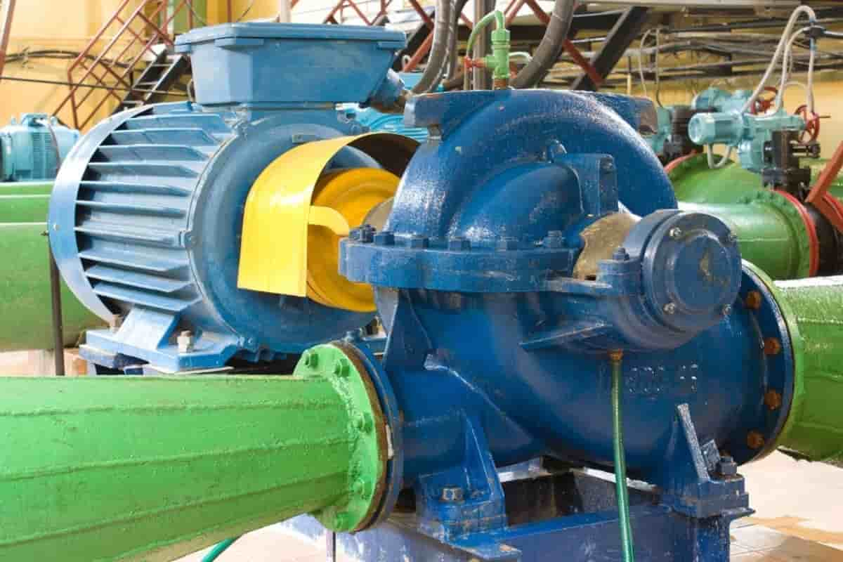
centrifugal pump working principle
Example: Calculating the efficiency of a pump
Predicting Pump Head Using this example, we will demonstrate how to
- Planned evacuation
- The power of water
- A pump's head
- Functioning of centrifugal pumps in series (booster)
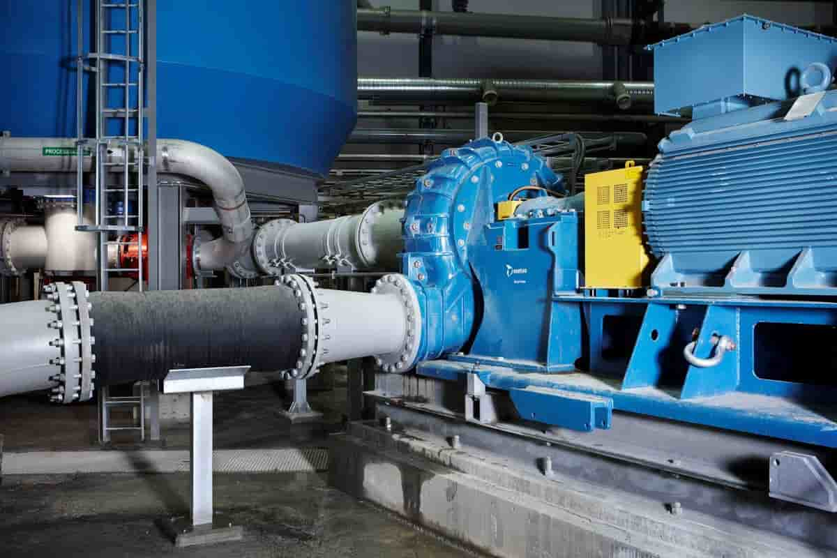
In order to enhance the volumetric flow rate or make up for significant or minor losses, centrifugal pumps are frequently used in parallel or in series.
When fluid is introduced into the system at a very high pressure, centrifugal pump series operation is utilized to overcome a significant system head loss or to accomplish a significant pressure rise (for example, high pressure safety injection systems in PWRs where multistage pumps are used).
The discharge pressure of a centrifugal pump that is working in a closed loop is just the sum of the suction pressure and the pressure that the pump would typically create when operating at zero suction pressure. Therefore, when used in series, it can be used as a boost pump.
Two or more pumps will each create a head that is equal to the sum of its individual heads. From the first pump's input to the second's exit, the volumetric flow is constant. Multi-stage pumps are made to achieve a larger pump head in real-world applications.
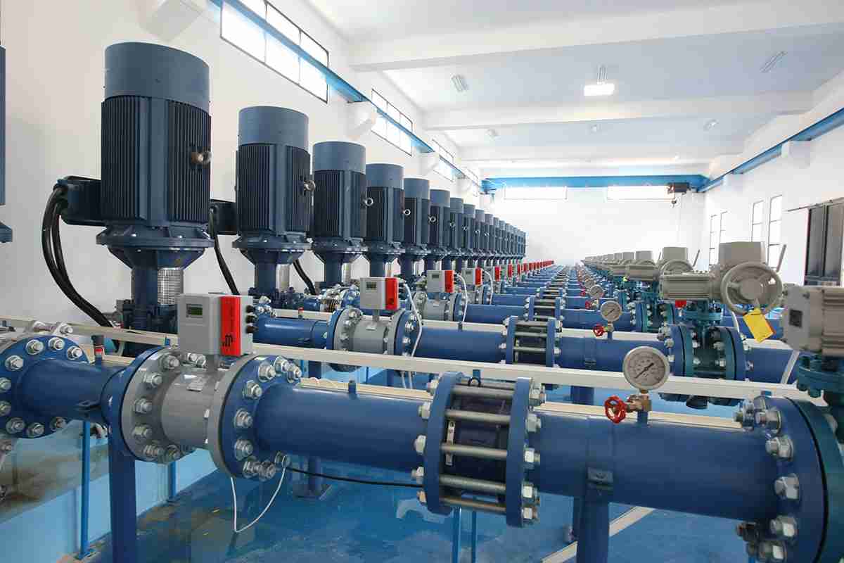
Operation of centrifugal pumps in parallel
To improve the volumetric flow rate in a system or to make up for significant or minor losses, centrifugal pumps are frequently employed in parallel or in series.
To boost the system's flow rate, centrifugal pumps are operated in parallel. Pumps that are running simultaneously draw their suction from a shared head and discharge to a shared discharge. At any given time, the flow roughly doubles while the head barely changes.
The volumetric flow rate is less than twice as high as the flow rate attained with a single pump, it should be emphasized. This is brought on by a larger head loss in the system as a result of a higher flow rate.
Centrifugal Pump Specifications
A pump with certain specifications like a centrifugal one that is chosen and verified for normal operation will typically function near to the optimum value (BEP), with low mechanical equipment power consumption and minimal vibration, which translates into strong reliability.
Reliability and efficiency are closely related in many aspects of pump selection.
There are many various types of pumping applications, and each one has its own requirements as well as penalties for not meeting them or for premature pump failure.
As a result, it is impossible to generalize how a pump should be chosen or assessed for operation and performance; instead, this article concentrates on choosing a pump that operates in a busy location.
To achieve the goal of efficient and effective pumping, (POR) with a positive suction head (NPSH) upper room required a net positive suction head (NPSHR) and appropriate vibration.
General criteria or specifications for pump margin NPSH, ORP, and permissible vibration are provided by three national standards for the United States.
The oil and gas business and the chemical industry, for example, have specific norms and criteria that must be followed in addition to the basic advice offered here.
centrifugal pump price
Region of operation
POR is the ratio of the flow rate on both sides of the BEP pressure at which the hydraulic efficiency and efficiency of the pump is not severely reduced. A rotodynamic pump's ORP varies based on its design, so to get the ORP for a particular pump, consult ANSI/HI 9.6.3.
To choose a pump that will function within its POR, you must first ascertain the system's required maximum and minimum flows. The system line(s) for operation ought to be created to indicate the system's length under typical operating circumstances.
An illustration of the static head (i.e., source-to-level or pressure differential) and friction (i.e., loss brought on by fluid pressure) system needs is called a system line.
The "needed head" of the pump for a specific rate of pumped water is the same as the system head, which is stated in feet (ft) of pumped water.
The rating system is crucial since the pump will run at a speed that exceeds the system's capacity.
In an open system, a dynamic system can be changed with a constant variable to produce an active zone rather than a single point, such as a changeable level between a source and a destination.
a desirable swimming area
It is necessary to determine the Net Positive Suction Head Available at the System's Surface. NPSHA is a full suction head for the pump source that operates above the water-pumped air pressure.
The NPSHR is the highest NPSHA allowed by the manufacturer, which is necessary for the pump to work as intended at the pump's stated pressure, pressure, and fluid level.
With flow, the pump's NPSHA typically lowers while its NPSHR often rises.
For their published NPSHR values, the majority of pump manufacturers utilise the industry-standard cavitation pressure factor (NPSH3) of 3%.
This indicates that cavitation occurs if the pump operates with an NPSHA equal to its NPSH3 and that this cavitation reduces the efficiency by 3%.
centrifugal pump definition
The user should give the required distance above NPSH3 as described in ANSI/HI 9.6.1 depending on the kind of pump and presume that reported NPSHR is based on NPSH3 unless otherwise instructed.
Centrifugal pump selection
Choose a pump, multiple pumps, or series pump with one or more specified lines, depending on the minimum flow rate required, that satisfies the requirements when operating within the pump's POR and whose NPSHR is sufficiently low below the NPSHA.
Refer to Figures 3 and 4 when selecting a pump manufacturer from a list. A family tree or selection chart is shown in Figure 3.
For each pump type and manufacturer, the selection chart displays the normal operating range for various pump sizes at a certain pressure. The selection chart can be used to compile a list of pumps for suitability testing.
The manufacturer's specifications can be consulted after determining the proper pump size for a 1000 gpm job and 100 feet of head in order to help choose the optimum pump for the application.
A sample of the curve reported for a 5 6 11 pump working at 1770 rpm is shown in Figure 4. The website of the pump's maker contains a wealth of information relevant to this use, including the following:
The point of reduction for the wheel diameter falls between 10 and 10.5 inches.
The pump has an efficiency of 86% at BEP and 85% at rated time.
The input power of the pump will be between 25 and 30 horsepower (hp) at the given flow, although a 40hp motor may be needed to make sure that things aren't overloaded at the end of the line.
At the fixed point, NPSH3 is between 9 and 10 feet, and at the line's conclusion, it is 20 feet.
The graphs on this graph are for water at 68°F, so take note of that. The energy estimates will alter depending on whether the necessary water has a specific gravity that is higher or lower than water at that temperature.
Additionally, for optimum pump selection, the flow rate, head, and capacity must be changed in accordance with ANSI/HI 9.6.7 Rotodynamic Pumps - Guidelines for Effect of Liquid Viscosity on Performance if the application calls for temperatures colder than those required for the test fluid.
centrifugal pump for sale
As was already indicated, the system can need a set of common activities to fulfil the criteria. It should be thought about how to control the pump in the best possible way to consistently and effectively fulfil all specified operating conditions.
Typically, pumps are controlled to maintain conditions like level, pressure, temperature, or pressure. These values can be managed by varying the pump speed, bypassing the flow, flow rate, or pausing the pump periodically.
These methods each have benefits and drawbacks, thus it is possible to combine them.
The selected control strategy should take into account trying to keep the pump as much as feasible inside the POR. The pump speed range and limiting system are shown in Figure 5. The ORP in this instance is represented by the 80% efficient lines.
The pressure range when operation is in the POR grows from 100% pressure to roughly 80% by selecting the pump at 1% pressure where the system differential pressure is linked to the pump line to the right of the BEP.
Also take note that the combined flow from the pump and the pump limiting system is almost at the minimum flow permitted when the pump speed is decreased below 80% pressure.
Keep the pressure low when utilizing a high pressure pump as a control method to prevent dependability problems brought on by low water levels.
Control tests and functional tests
In order to confirm satisfactory hydraulic performance, NPSH3, or pump uniformity, manufacturer tests can be ordered after the pump(s) have been chosen and have been confirmed to fulfil the system requirements.
For hydraulic testing, users should consult ANSI/HI 14.6 Rotodynamic Pumps.
How useful is this article to you?
Average Score
5
/
Number of votes:
1