Wire to board connector is used to connect wires and different types of cable or a set of discrete wires to a printed circuit board (PCB).
These connectors, which are usually medium and low voltage, are an efficient and cost-effective way to deliver power and signals to PCBs in automotive, industrial, lighting, and communications products.
Commercial electronic equipment and household appliances also often use wire-to-board connectors.
The needs of the application will dictate the connector style chosen, as there is no "standard" wire-to-board connector design.
Depending on the manufacturer, some have a low profile fit for tight spaces and different locking mechanisms such as friction locks, full locks or quick disconnects.
Others have locking handles or a snap-on connection to ensure that the cords are held securely in their sockets.
While many connectors are surface mounted on a PCB, others have pins that pass through the PCB and are soldered to the other side.
Wire-to-board connectors are specified by characteristics such as housing size, material, number of contacts, stack height (connector height measured from the board), contact length, and number of contact rows.
They are also specified in terms of leg spacing, which is the distance measured between the centers of two conductors.
Wire termination also varies by wire size and number of contacts.
For example, connectors that handle high power typically have crimp contacts that are secured with some tool.
Other types, such as mass termination connectors that hold 20 or more wires, can be designed for use in automated soldering systems.
Another recent development is a new generation of ultra-compact connectors with a profile of less than 1.5 mm, compatible with automated surface mounting in high-volume production.
To ensure reliability, these miniature connectors typically have gold-plated contacts and strain relief.
With today's wire-to-board connectors available in so many sizes and styles, design engineers have more options than ever to select the right power and signal transmission system for their end product.
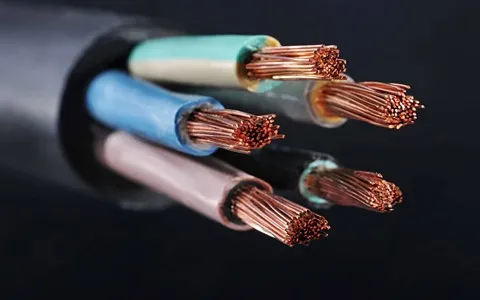
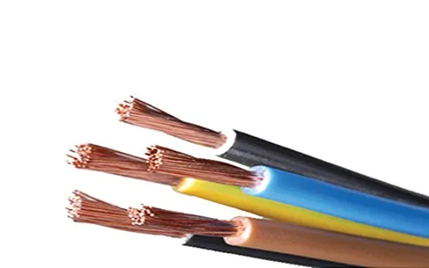
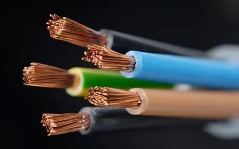
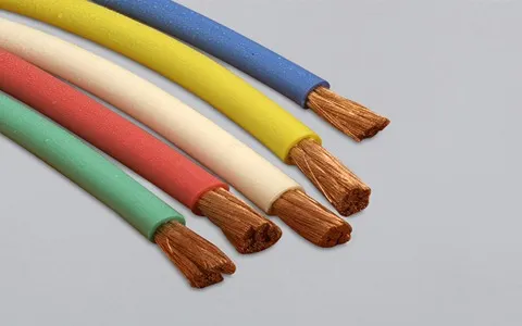
Medium voltage cable for board connector
The medium and low voltage wire and cable as the connector, used for connecting the main board with other parts, come in different types.
In basic wiring installation techniques, there are three types of cable connectors: twisted pair connectors, coaxial cable connectors, and fiber optic connectors. Cable connectors typically have a male component and a female component, except in the case of hermaphroditic connectors, such as IBM data connectors. Usually plugs and sockets are symmetrically shaped, but sometimes they are key.