اتصال به اینترنت شما ضعیف یا قطع است.

Low Voltage Landscape Wire | Buy at a cheap price

Choosing the right wire and cable depends on their application but there is a standard chart that indicates the specifications and size and differentiates the low voltage from the high voltage wire and cable. Cables, components, and connections specific to these technologies are used for low current circuits. The ability to make these connections makes the process of installing low current systems such as telephone lines, fire alarm systems, CCTV, and burglar alarm systems much easier. A high-quality connection in these systems will reduce the amount of audio transmission (on the phone), images (CCTV camera system), (central antenna signal), and fewer errors. On the other hand, the weak currents in these systems lose their properties mainly under the influence of environmental factors, for example, in the cables of these systems, the length of the cables, the induced waves of electrical equipment, the surrounding magnetic fields and the cables adjacent to them, the temperature Elevation and even lightning can affect the quality of its work. Unlike light and socket wires, wire cross-section is an important factor when choosing conductors. Conductor cross-section is not so important in these types of systems, where protection of conductors and environmental factors are important in the selection of cables. The interference caused is important and the term cable is used for these systems because the conductors are separated from the surrounding environment by at least two shields. In this chapter, the definitions and common connections for low current systems are followed. Low voltage wire and cable size - Cable: The main cables in the weak current system can be divided into two categories: twisted pair cables and coaxial cables. Of course, fire-resistant cables and low-voltage supply cables for components and equipment in these systems can be classified under another category. - Twisted Pair: TP (Twisted Pair) The reason pairs of wires shine in these cables is that the conductors do not create a magnetic field around them and neutralize the effects of the noise they make. These cables are widely used in telecommunication circuits and can be divided into two types: unshielded (UTP) and shielded (STP). Coax cable: These cables have good immunity to interference and harmful environmental factors and their components are shown in the diagram below. This type of cable is used in TV aerials and CCTV systems. The two main types of these cables are RG95 and RG6. 
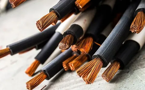
Power cables and fireproof cables: This cable is used in control circuits for tracking and fire alarm systems. Fire alarm circuits should not be interrupted during a fire. An example of such a cable can be seen in the picture. Low voltage cable size chart

Low voltage wire and cable size

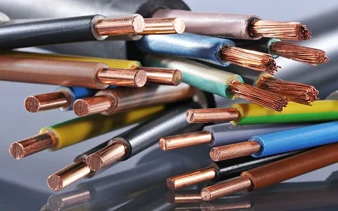
The different types of wire and cable, low, medium, and high voltage, are usually distinguished by size and cross-sections. 
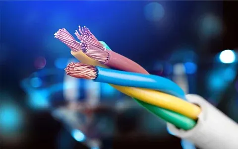
The low-voltage multi-core cable in the four-wire cable is a kind of cable. Normally, the cross-sectional area of ​​the three wires of the cable is the same, and the cross-sectional area of ​​the fourth strand is smaller. The smaller value of this wire is usually one grade compared to other wires, but in some cable sizes it is several grades less than others. For low-voltage and high-voltage cables, single-conductor cables are used by increasing the cross-section, because the construction of a 300 mm square three-conductor cable causes problems with the outer diameter. One of the factors that are effective in the life of a cable is its usage conditions. All safety conditions and instructions must be followed when laying cables on the ground. In addition, he also ensures that the cable's rotation radius is not less than 15 times the cable's outer diameter and that the cable's temperature is not lower than 5 degrees Celsius above zero. In important networks (DC and AC) there should not be only one line to supply all consumers (of course, in some cases this method is not practical), so there must be several main lines, and Distribution of consumers in proportions divides the meaning and type of their work in these areas. On the other hand, when the distribution network is normal and many supply lines are widely branched from it, a large voltage drop occurs in the terminal branches. Low voltage wire size chart One of the ways to reduce the voltage drop in networks is to distribute their current from both sides. In this case, the lowest potential occurs at only one point on the line, which is much lower than if the same network of the same cross-section is supplied only from one side. This point of lowest potential (ie the largest voltage drop) is called the deep point. Detecting and determining deep points is one of the most important points in closed network processing. Here we will limit ourselves to mentioning some of the ways in which depth can be easily found.

  • At the deep point, the voltage drop will be greatest.
  • At the deep point, the network voltage will have the lowest value.
  • At the deep point, the flow direction of the network changes.

There are two types of closed networks:

  • Closed network with two power sources (network powered from both sides)
  • Closed network with power supply (ring network)

Distribution network with variable cross-section If the distribution network is natural, with many branches, and at the same time fixed, it is possible to have a network with a variable cross-section. There are limitations to using variable share networks, some of which are listed below:

  • In a distribution network with variable parts, it is not possible to increase the power of consumers.
  • In distribution networks with a variable cross-section, the number of branches cannot be increased.
  • To connect the two parts of the network at the point where the cross section changes, there will always be a problem.

Conductivity and its skin effect in conductors Conductor: Any material that conducts electricity well is called a conductor. Common conductors are made of nearly pure copper or aluminum or special alloys with acceptable flexibility. The cross-section of the conductor is made in different sizes and shapes depending on the amount of current passing and the type of application. 99.5% of copper conductors are used for electrical installations in buildings. The properties of copper include low electrical resistance, excellent electrical conductivity, resistance to atmospheric influences, good mechanical strength, and ductility, while the properties of aluminum include good mechanical strength, ductility, lower electrical conductivity than copper, and cheaper than copper. Aluminum also has disadvantages, such as lack of resistance to atmospheric influences, resulting in oxidation, and another is its low yield strength. Conductor skin effect: The skin effect is the inherent tendency of alternating current to be distributed in areas closer to the surface of the conductor. This distribution flows at a distance from the surface according to the frequency of the alternating current, called the skin depth. The skin effect increases the effective resistance of a conductor. At microwave frequencies (between 0.3 and 300 GHz), most of the current pass through a very thin layer near the surface. Shallow skin depths in this area indicate that coverage close to the surface of the conductor will be considered, rather than its depth. The table below shows the surface depth of copper at different frequencies.

Low voltage cable size chart

The standard cart of the low voltage wire and cable is organized by calculating the numeric specification of the product, indicated with size of wire and cable, in standard condition. 
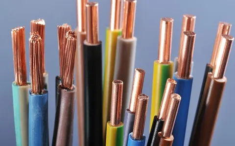
In fact, a cable refers to various metallic conductors capable of conducting an electric current and being isolated from the surrounding environment by an insulating material. The cross-sectional area of ​​a cable conductor and the type and thickness of insulation and other layers within it depend on the environmental conditions, the amount of current, the voltage, the type of ground and the applied mechanical force to the cable. The chemical environment and other weather conditions, of course, the energy to be transmitted or distributed, the ambient temperature and the operating temperature of the cable are all valid for the cross-section of the cable. On the other hand, the cross-sectional area of ​​the current conductors starts from 1.5 mm2 and extends up to 1000 mm2. But how to calculate the cross-section of the cable, what is the cross-section in general? A cross-sectional area in a geometric definition, the intersection of a shape with a line or object in two-dimensional space and an intersection with a plane or other in three-dimensional space, can create a special cross-sectional area. In a simpler definition, parallel cross sections are created when an object is cut into pieces. The cross-section of the cable is also the same, when a section of the cable is cut vertically, the cross-section of the cable is visible. These cross-sections can be used in various forms, with the conductor cross-sections being circular, sector-shaped and sector-shaped. Now we will see how to calculate the cross section of the cable based on various factors. To get the cross-section of cables and wires, you should pay attention to things like permissible current, short-circuit current and finally the maximum voltage drop, as you can easily find the required cross-section from these points. However, the determination of the cable cross-section according to the permissible current of the cable is carried out in two different parts of the single-phase and three-phase circuits, so we must first check the amount of current in this series of circuits. According to the calculation formula I=W/V.Cosφ for the amperage on the cable, the amperage can be easily obtained in a single-phase circuit. W is the input power, V is the circuit voltage and finally Cosφ, the power factor. In general, all units are assumed to work together. Although in real conditions, all devices will not work at the same time. Therefore, the coefficient kd is added to the current formula. This coefficient is obtained by dividing the maximum power consumption at the same time by the total power of the load, which is called the consumption coefficient or the simultaneous coefficient The above formula is in the form of I=kd.W/V. Cosφ transformation. If the motor is operating at its rated capacity, its current is equal to I=w/√3.η. Cosφ is that in a three-phase motor, the current of the motor can reach 5 to 7 times its rated value at the moment of starting, but considering the short flow time of the current, it has no effect on the cross section. Note that by using the current of any motor or electrical device, you can also calculate the cable cross-section of a three-phase motor and select the desired power line.

Low voltage wire size chart

The temperature is an important factor, affecting the numeric specifications of low voltage wire in the standard chart, depending on the size of wire, which can also affect the voltage drop. The voltage drop on the steady-state cable uses the formula Vd=√3.I.(RCosφ+XSinφ)L, which includes the Vd voltage drop, R the cable resistance of each phase under alternating current, I the maximum steady-state current , X the reactance of ​​each phase cable at each I phase Cosφ is also the power factor at full load and finally L is the length of the cable. The voltage drop must not exceed the value measured in the standard. According to the standard, the motor voltage drop is 5% during normal operation, 15% during start-up, 5% when the motor is loaded and 3% during light gearing. Note that as previously mentioned, the voltage drop must be checked and measured during start-up due to the high current flow during activation. If wires and power cables are laid on the ground, the cross-section of the power cables should be measured based on the voltage drop in the circuit and other important parameters. Note, of course, that in order to obtain the cross-section, we must examine the voltage drop in single-phase and three-phase circuits. In a single-phase circuit, the value of the cross-sectional area from the voltage drop and ground wires is obtained according to the formula a=200ρℓICosφ/αV, where α is the standard allowable voltage drop percentage, which should not exceed a certain limit and belongs to the prescribed part. And the formula we talked about earlier is very clear. ρ is the resistivity of the cable conductor, a is the cross-section of the wire, ℓ is the distance, Cosφ is the power factor, and finally V is the voltage. This formula can be used when the supply line loads are the same, otherwise to get the cross-sectional area, calculate the cable cross-sectional area for each load line and add them together. If the circuit is a three-phase system, note that the neutral or ground current is zero in equilibrium. In the case of balanced loads, since the phases are similar, it is sufficient to check the cross-section of only one phase and perform the calculation.

How useful is this article to you?

Average Score 5 / Number of votes: 1

Comments (0 Comments)

💰 Tenfold your income 💎