Electric Slurry Pump for Sale with Solar Panel or Diesel Power Supply
The electric submersible slurry pump is an industrial-grade pump that has a high head and a large discharge volume.
It is a powerful piece of equipment.
Electric slurry pump for sale
It is built to function with a multi-power supply such as diesel or solar panels, dependably twenty-four hours a day, seven days a week, even in the severe settings that are typical of major construction projects and mines.
For optimal durability, the electric slurry pump's cutters are cast from a high-chrome alloy, as are the mouth ring and the impeller.
This ensures that all three components are constructed from the same material.
Additionally, the one-of-a-kind technology that our company has developed, which constantly changes the clearance that exists between the mouth ring and the impeller, has assisted in lowering the amount of performance loss that is caused by wear.
Seal pressure relief apertures have better long-term reliability because they relieve the pressure that is being applied by the pump to the mechanical seal.
Additionally, the pump is constructed with a side discharge that features a spiral pattern to facilitate the passage of solids.
In a variety of commercial and manufacturing environments, centrifugal slurry pumps are a common piece of equipment.
Within a centrifugal pump, the fluid is propelled forward by the rotation of one or more impellers, which is assisted by the centrifugal force.
There is not a single centrifugal slurry pump that is perfect in every way.
Many low-quality centrifugal pumps can only handle a certain amount of water before they reach their capacity limit.
This is the maximum quantity that can be accommodated within their housing and by means of their impellers.
Both centrifugal slurry pumps and industrial centrifugal pumps are exceptionally long-lasting when compared to other kinds of pumps.
Due to the robust nature of their construction, they are resistant to corrosive and abrasive substances.
The fundamental objective of a centrifugal slurry pump is to move slurries, which are defined as mixes of solids and liquids, from one location to another.
Because of their dependability, centrifugal slurry pumps are preferred when working with liquids that have a low viscosity and high flow rates.
Their applicability spans a wide range of industries.

Submersible slurry pump
Due to the company's extensive product catalog, DAE Pumps is able to supply centrifugal slurry pumps in every conceivable size and configuration.
These industrial centrifugal pumps are more than capable of managing the difficult task of pumping particles that are both heavy and abrasive in nature.
They are utilized in a variety of industries, including mining, the manufacturing of pulp and paper, farming, construction, oil and gas extraction, and agriculture, amongst others.
The fact that we sell dredge pumps, submersible slurry pumps, self-priming pumps, and flooded suction pumps for such a wide variety of applications is a testament to the adaptability of these products.
When emptying cesspools, one of the most challenging tasks is to remove the most uniform possible masses.
This is because the liquid manure constituents differ from one another in terms of the nature of their components and the precise weights of each component.
It is important for the contents of the cesspool to stir up the heavier constituents that have settled at the bottom of the pit so that they can mix with the liquid and semi-liquid components that are located higher up in the pit.
Evenly interspersed masses. It is already common knowledge that individuals who were responsible for the provision of filling the liquid manure tanks were those who made this possibility attainable.
It is necessary to install special pumps with an agitator that generates a sharp liquid jet that is aimed towards the bottom of the cesspool, and to so far capture all soil deposits with the help of a drainage nozzle that is rotatably placed and guided in a circle around the floor area.
This version had the disadvantage that, in addition to the increased power consumption required to achieve the circumferential leadership of the drainage port, the device was not only very complicated and expensive, but also very prone to fouling, clogging, and rusting of the movable ones as a result of their constant exposure to water and other liquids.

Submersible slurry pump
The lifespan of the parts was rather limited, and they incessantly caused disruptions in the operation of the machine.
These disadvantages of the known electric liquid manure pumps with built-on agitators are avoided by the invention that the outflow nozzle of the conical distribution box is connected to the centrifugal pump with a wreath arranged, in their position invariable nozzles is provided such that the liquid manure sucked in by the centrifugal pump radial is pressed against the bottom of the cesspool.
It is the invention that the outflow nozzle of the conical distribution box is connected to
The number of nozzles that are attached to the outflow connection of the agitator can range from three to four or even more, depending on the size of the cesspool.
The outlet nozzle itself is located directly on the distribution box that is built into the riser pipe of the pump.
This distribution box has a flap that can be manually operated to control the supply of the sucked mass to the jet nozzles or controls to the filling pipe from which the liquid manure flows into the liquid manure barrel.
An embodiment of the invention is illustrated in the figure.
More specifically, the drawing depicts the subject of the invention in a side view, as well as a horizontal section via the outlet of the agitator.
The outflow nozzle and distribution box are depicted here on a slightly larger scale.
A distribution box G is installed in the climb and fill tube A, which also serves as a carrier for the electric motor B that is attached to it.
This box houses a control flap that is rotatably housed and can be controlled with a handle by means of a rod M J H.
The climb and filling tube A also serves as a carrier for the electric motor B that is attached to it.
This control flap directs the flow of manure either into the pipe A, from which the manure flows into the slurry tank, or into the agitator nozzle K, to which multiple output nozzles L are conically attached.
Either way, the manure is eventually discharged into the slurry tank.
The following is a brief explanation of how the device in question works: the impeller E draws the liquid manure into the housing D, and the housing D is then used to press the dung into the distribution box G.

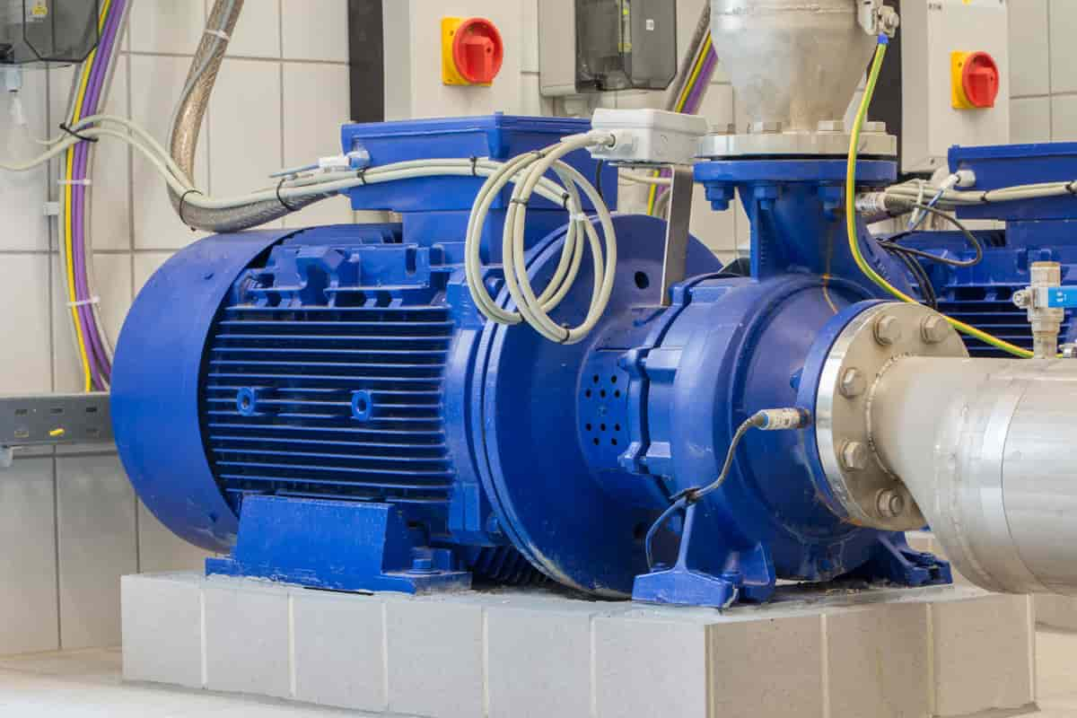
Centrifugal slurry pump
In order to be able to convey even masses of the liquid manure into the cesspool, the contents of the cesspool need to be stirred up prior to the pipe A being used to fill the cesspool with the liquid manure.
This is done before the pipe A is used.
This is accomplished when the operator pulls back on the handle M, which causes the rod I to move downward.
As a result, the control flap H covers the opening that leads to the pipe A, and the aperture that leads to the agitator connector K is opened.
Now, the liquid manure is being forced through the jet nozzles L, which have been placed in such a way that they will shoot a concentrated stream of liquid in every direction around the cesspool.
This causes the more viscous contents of the cesspool, which are known to have settled to the bottom of the pit, to be stirred up.
In the event that this has been completed to an adequate degree, the operator will draw the handle M of the rod J upwards.
This will cause the opening of the outflow pipe A to be released, and the agitator connector K will be closed.
It is now possible to transport the liquid manure mixture into the barrel designated for liquid manure.
Accordingly, the invention consists of the manure being pumped in a circuit by firmly connected nozzle-shaped outflow nozzles, which radiate in all directions of the cesspool, thereby stirring up the denser contents of the cesspool.
These nozzles radiate in all directions from the cesspool.
The effect that was intended is guaranteed by the outflow nozzle's design, which is formed like a nozzle.
In addition to this, it is essential that the nozzle-shaped outflow nozzles that are located after Squirt spread out in all directions within the pit, and that they are not situated in a way that allows them to be moved.

How useful is this article to you?
Average Score
5
/
Number of votes:
1


