Buy the latest types of solid wire cable
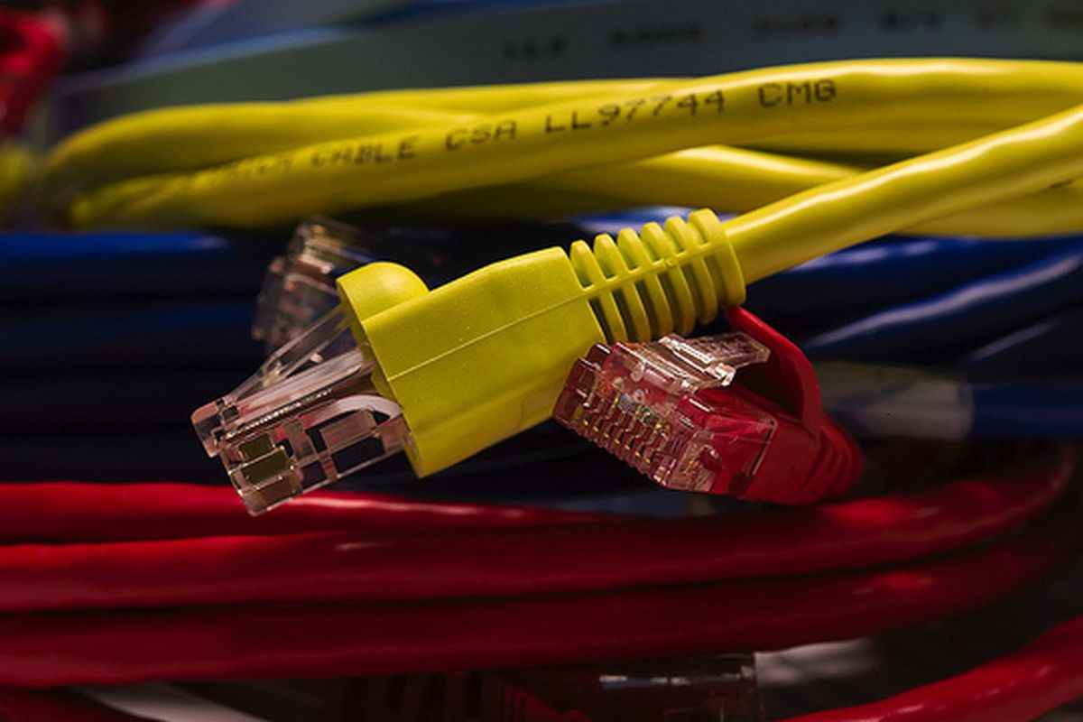
Ethernet cables have many types with different cords. Most of these cables are found in solid and patch forms of cord and wire. What really interesting about these cables is that they can come with different connectors, the RJ-45 is one of them.
solid wire cable
The use of Ethernet patch cords is rapidly becoming more commonplace as Ethernet systems become increasingly flexible and cost-effective in their ability to transmit voice, data, and multimedia over integrated networks.
As a result of this, Ethernet patch cords are quickly becoming a part of our everyday experience.
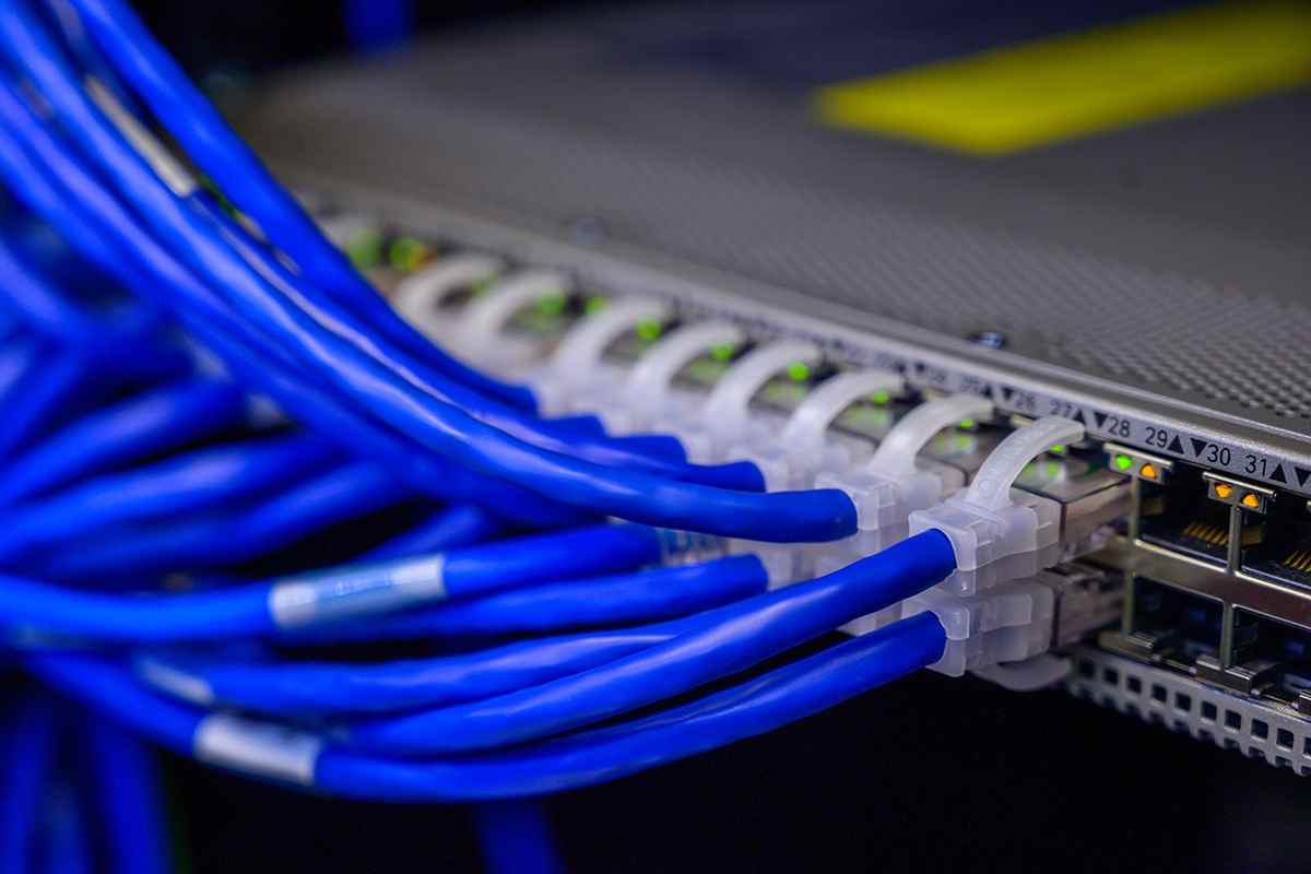 We are able to spot them in the work areas of commercial and educational facilities, where they trail away from the backs of computers and onto wall plates and other computers.
If we follow their course, we will watch them wind their way down the pathways leading from wall plates to patch panels, and then we will see them emerge once more from the patch panels and make their way to adjacent hubs or switches.
However, despite the fact that the modular qualities and abundance of patch cables give the impression that their application can be applied in any setting imaginable, there are significant distinctions between each of them that can hinder their capacity to be interchanged with one another.
The changes in the wiring configurations of their cable conductors and connection pins are the source of some of these discrepancies, and it is these distinctions that will be addressed in more detail in the following paragraphs.
- Patch Cords for Ethernet and RJ-45 Connectors both can be found here.
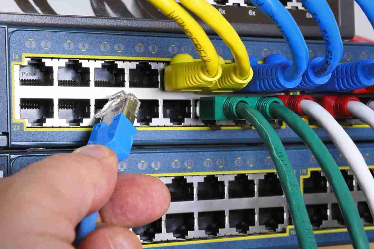
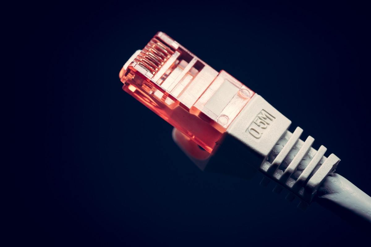
Patch cables for Ethernet are flexible leads that are equipped at each end with an 8P8C ("8 positions, 8 conductors") connector plug.
These cords are used to connect two 8P8C jacks that are identical to one another. The 8P8C connectors that are used in Ethernet systems have taken on the common name RJ-45, which is an FCC designation for a Registered Jack that also has an 8P8C configuration.
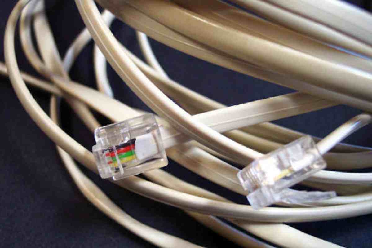
This is because the 8P8C connectors look very similar to the modular connectors that were initially used in telephone wiring systems.
These RJ-45 connectors and jacks come together to form a gendered, modular connector system that is used in Ethernet networks.
This system makes it simple and quick to relocate workspaces and alter network components. The male plugs and the female jacks are kept together by a spring-loaded tab, which is called a hook.
This tab ensures that the plugs and jacks remain firmly in place when in use, but also makes it simple to unplug them when adjustments need to be made to a network system or a work area.
This modularization is made possible by the eight conducting pins that can be seen on top of RJ-45 plugs and immediately inside the tops of RJ-45 jacks. These pins can also be found in RJ-45 jacks.
An 8-conductor Ethernet cable can transfer electronic data from one jack to another through its 8 connector pins if the ends of the conducting wires in a patch cable are connected to individual pins in its two RJ-45 end-plugs.
solid wire uses
This can be accomplished by connecting the ends of the conducting wires in a patch cable to individual pins in its two RJ-45 end-plugs.
- Patch Cords for Ethernet and Unshielded Twisted-Pair (UTP) Cabling
UTP cable, also known as unshielded twisted pair cable, is typically utilized in the construction of patch cords for usage in Ethernet networks.
UTP cable is made up of eight insulated copper-core conductors that are organized into four pairs. The conductors in each pair are then twisted together along the length of the cable.
Conductor pairs and individual conductors in UTP cables are denoted by a color code that designates a primary color (blue, orange, green, or brown) for each of the four twisted pairs.
This color code represents the conductor pairs and individual conductors in UTP cables. The insulation around a conductor that is part of a pair can either be white with a primary color striped across it, or the primary color itself.
All of the conductors are able to be identified in this fashion, first as members of a particular twisted pair and then as individual members of that pair.
The conductor pairs are numbered from 1 to 4, with the blue pair equivalent to Pair 1, the orange pair relating to Pair 2, the green pair corresponding to Pair 3, and the brown pair belonging to Pair 4.
The individual conductors in UTP cables can either be solid copper-core wires that have a predetermined thickness or bundles of fine copper wire strands. Both of these types of conductors are copper.
Patch cords nearly typically make use of stranded cables, despite the fact that solid-conductor cables are significantly less expensive and considerably simpler to terminate.
Because of this, the cable is more flexible and durable than it would be otherwise due to the stranding of the conductors.
Due to the additional flexibility that patch cords provide, it is possible to easily switch them between different wall outlets and patch panels, as well as conveniently route them through tight places in between connected pieces of equipment.
Because of their exceptional resilience, they are able to withstand repeated bending while retaining their flexibility and integrity, which results in a longer lifespan.
solid wire price
This is of the utmost importance at the connector ends of the cable because this is where the conductors are subjected to the greatest pressures as a result of frequent handling, bending, and moving around at the interface between the cable and the connector.
- What's the Deal with All This Twisting Regarding Twisted Conductor Pairs?
A balanced circuit is formed by the twisted conductor pairs that are seen in UTP cables.
This is due to the fact that the voltages of each member in a particular pair have the same amplitude, which refers to the same magnitude of the voltage; but their voltages are opposed to one another in phase (one voltage is positive, and the other is negative).
The uniform twisting of each of these balanced pairs helps to reduce electromagnetic interference (EMI) and radio frequency interference (RFI), both of which can be caused by other conducting pairs within the cable or by equipment located in the environment of the cable.
Crosstalk is a form of electromagnetic interference that occurs when the conductor pairs included within a twisted-pair cable interact with one another.
When the electromagnetic field generated by one pair is large enough (when the signal strength of the pair is strong enough), it can cross over to the position of a neighboring pair, which is when crosstalk takes place.
This "talking" is more accurately described as a form of co-mingling of the two fields that takes place as a result of a constant exchange of energy between them. During each energy exchange, certain components of each signal are transmitted to the other field.
The outcome of all of these exchanges will be that the finer details of the smaller signal, which are always the excellent parts, will be cancelled out, or there will be an increase in the quantity of noise that is around the smaller signal.
External sources of EMI and RFI interfere with signals in a similar manner, further distorting or degrading them as they travel along cables that are located near "noisy" office and communication equipment.
These interferences are caused by electromagnetic induction and radio frequency interference, respectively.
When individual conductors are twisted together to form conducting pairs, the size of the electromagnetic fields that are produced by the current and that surround the conducting pairs is reduced.
This reduces the influence that the conducting pairs have on signals that are traveling through other conductors by limiting the field interactions between the conducting pairs.
Due to the fact that the pairs are also balanced, meaning that the two wires that make up each pair carry signals with equal and opposite polarity, the twisting of the wires ensures that each pair is subjected to an equal amount of interference from fields generated by other pairs or external sources.
When you subtract the magnitudes of the signals with opposite polarity from each other, you get the total magnitude of the transmitted signal as it arrives at the other end of the cable.
wire cable connector
This procedure also automatically cancels out the interference signals that have the same magnitude but different polarity.
In this manner, the twisting and stabilizing of the conductors in UTP cables can effectively remove the noise within transmitted signals without removing or troubling the signals themselves.
This is made possible by the fact that the noise components are contained within transmitted signals.
A cable's resistance to EMI and RFI improves in direct proportion to the number of times its conductors are twisted. When the number of twists per unit length (also known as the twist rate) is changed across the four different pairs, this immunity is improved even further.
For instance, makers of higher-grade cables utilize differences in the twist rates of individual conductor pairs. They use a unique twist rate for each of the four pairs in order to reduce the amount of crosstalk that occurs between the pairs.
However, adding any more variability to the twists than this would result in a decrease in cable performance rather than an increase. This is because signals flowing along the various conductors that make up a pair will no longer be impacted equally by the interference fields.
As a consequence of this, there will be interference components for the two signals that are unequal in amplitude, and the subsequent subtraction of the signal voltages will only partially cancel out these interference components.
Therefore, it is necessary for each of the pairs to maintain the same twist rate throughout their whole; failing to do so will result in the loss of any additional immunity that might have been gained by applying various twist rates to each of the pairs.
Wrapping each conductor pair with a foil shielding further decreases the crosstalk between pairs, and wrapping all four of the twisted-pairs in a foil or braided metallic shield decreases a cable's sensitivity to EMI and RFI in noisy cable settings.
STP cables, also known as shielded twisted pair cables, use both of these types of shielding, which gives them the best possible protection to interference of any kind.
FTP (Foil Twisted Pair) and ScTP (Screened Twisted Pair) cables use only the outer foil or braided-conductor shielding, which gives them enhanced immunity against external EMI and RFI.
However, they do not provide any additional protection against crosstalk in comparison to an equally-constructed UTP cable.
- Applications Utilizing Ethernet
The 10Base-T and 100Base-T standards were developed by the IEEE to define the electrical and physical characteristics of twisted-pair cabling that can be utilized in Ethernet connections operating at 10 Mbps (Megabits per second) and 100 Mbps, respectively.
wire cable organizer
These two Ethernet connections use wire pairs 2 and 3 to transmit and receive data.
These wire pairs correspond to the orange and green twisted pair conductors and pins (1,2) and (3,6) in the RJ-45 connector plugs and jacks. The "T" in Ethernet stands for "twisted pair," and the "T" in "twisted pair" stands for "twisted pair."
One of these balanced conductor pairs is utilized for the purpose of transmitting information, while the other is utilized for the purpose of receiving information.
It is common practice to mark the two pairs as follows: (TX+, TX-) for the transmitting pair and (RX+, RX-) for the receiving pair.
Other two cable pairs—corresponding to the brown and blue cable pairs and the remaining four connector pins (4,5) and (7,8) on RJ-45 connectors—are not used for 10Base-T and 100Base-T connections.
This is the case for both connections. Because of the development of Gigabit Ethernet, also known as 1000Base-T, all four conductor pairs are now utilized in the simultaneous transmission and reception of information.
- 568A and 568B are two different standards for wiring.
Electronics Industry Association and Telecommunications Industry Association wiring standards 568A and 568B specify two different RJ-45 pin assignments for the orange and green wires pairs in Category-type twisted-pair cables.
These standards were developed by the Electronics Industry Association and the Telecommunications Industry Association, respectively.
Having two separate conductor/pin combinations may at first appear to be problematic due to the fact that these are the same conducting pairs (pairs 2 and 3) that are utilized for Ethernet connections.
However, when it comes to Ethernet patch cords with connections wired according to the same standard on both ends, the real variations between them are surprisingly minor. This is true when looking at the wiring from both an electrical and a physical perspective.
The changing of the green and orange wire pairs is the only variation between the 568A and 568B specifications, as can be seen in the RJ-45 connector plugs and jacks illustrated below.
When a plug or jack is wired according to the 568B standard, the striped green and solid conductors that are assigned to pin pair (1,2) in the 568A standard are assigned to pair (3,6) in the 568B standard.
and the striped orange and solid orange conductors that are assigned to pin pair (3, 6) in the 568A standard are assigned to pair (1,2) in the 568B standard.
Within the two conductor pairs, this represents a symmetric swapping of the stripe-for-stripe and solid-for-solid configurations.
Additionally, this represents a symmetric swapping of the pin positions on the RJ-45 connection plug or jack that correspond to these configurations.

How useful is this article to you?
Average Score
5
/
Number of votes:
1
 We are able to spot them in the work areas of commercial and educational facilities, where they trail away from the backs of computers and onto wall plates and other computers.
If we follow their course, we will watch them wind their way down the pathways leading from wall plates to patch panels, and then we will see them emerge once more from the patch panels and make their way to adjacent hubs or switches.
However, despite the fact that the modular qualities and abundance of patch cables give the impression that their application can be applied in any setting imaginable, there are significant distinctions between each of them that can hinder their capacity to be interchanged with one another.
The changes in the wiring configurations of their cable conductors and connection pins are the source of some of these discrepancies, and it is these distinctions that will be addressed in more detail in the following paragraphs.


