This tip is so close to me that in order to maximize output, high-pressure gas hydraulic pumps are constructed to have a high degree of efficiency while also being near a high bypass pressure. WKL class pumps come in a wide variety of sizes and configurations in Home Depot stations, ranging from compact, portable, and high-performance mobile designs to large, high-capacity power units. When it comes to providing hydraulic pressure, gasoline-powered hydraulic pumps are the way to go. The GDI high-pressure fuel pump is technologically upgraded. The high-pressure GDI fuel pump is responsible for generating sufficient fuel atomization pressure. This is required for the engine to function correctly. The GDI system is equipped with two gasoline pumps:
- They inject fuel into the tank responsible for supplying the engine with sufficient fuel.
- The GDI high-pressure fuel pump is responsible for generating sufficient pressure.
The engine must mechanically drive the high-pressure GDI fuel pump. Typically, the camshaft drives the high-pressure GDI fuel pump. The pump functions while the engine is operating.  This design lines the fuel pump with the engine with precision. This guarantees that the engine continuously receives the fuel pressure necessary for optimal operation The design of GDI high-pressure fuel pumps is comparable to that of mechanical fuel pumps. However, they are more advanced. This component aims to pressurize fuel entering the fuel tank before its delivery to the fuel rail. A fuel pressure sensor is present in the GDI system. This sensor assists the Powertrain Control Module (PCM) in adjusting the quantity of fuel entering the pump's inlet. Typically, GDI high-pressure pumps generate roughly 2,000 psi. Sensors and PCM help maintain fuel pressure at the optimum engine level in real-time by regulating pressure. The following occurs when the tank pump provides gasoline to the GDI high-pressure fuel pump:
- Low-pressure fuel enters the GDI high-pressure fuel pump's intake.
- Attached to the control valve plate, the engine rail forces fuel into the pump chamber (inside the pump).
- The camshaft propels the piston into the chamber of the pump. This reduces the available space and forces the fuel into orbit. This will result in fuel "spraying" from the pump.
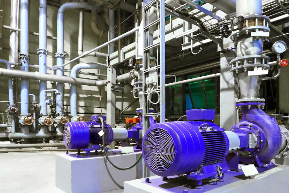
WKL Class High-Pressure Pump Home Depot
According to the Home Depot website, the high-pressure pump in WKL class is made up of a single chamber that has several sub-chambers within it. These sub-chambers include a suction chamber, a thrust chamber, and a number of chambers that correspond to the number of impellers. These sub-chambers are actually the same types of chambers that are found in the high-pressure pump. The bolts that are located on each floor serve to connect the individual levels to one another. As we have mentioned, each impeller is placed in its chamber with a screw, and behind the impeller is a diffuser whose task is to convert speed into pressure. The suction chamber is located on the left-hand side of the high-pressure pump. The water, or other fluids, enters the pump through the suction chamber. In point of fact, the diffuser is immobile while the propeller spins freely within it. The mechanical coupling may be found on the left-hand side of the propellers. Its function is to maintain the shaft's position within the housing so that there is no leakage and the pump does not fail. Additionally, there are four bearings located on the left-hand side of the mechanical coupling. These bearings are sometimes referred to as anti-depreciation bearings. After being pulled into the pump on each floor, the liquid then travels through an impeller before eventually emerging out the right side of the thrust tube. The provision of city water, the pumping of water and drainage and water supply for industrial uses, booster pumps, rain irrigation, the pumping of condensed water, the pumping of hot and cold water for industrial facilities, and firefighting, of course, are some of the numerous uses for these pumps. 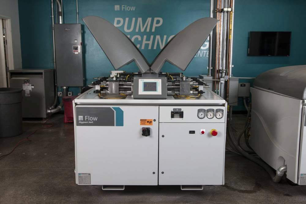
WKL Class High-Pressure Pump INC
In many pump classes like WKL, it is necessary for the high-pressure pump to have the capacity to INC and move fluid up to a height of one hundred meters or even more. In point of fact, boiler feeding pumps typically require additional height or head, particularly in power stations and large enterprises where the size of these pumps tends to be substantially larger than average. If we wish to talk about this height in a manner that is more specific, we need to keep in mind that the term "height" in the pump refers to the amount of static pressure that causes the fluid to be pumped up to a particular horizontal or vertical distance. The head, also known as the height that the fluid needs to travel in order to escape the high-pressure pump and seep out, is referred to as the static pressure. The high-pressure pump, as its name suggests, possesses a high static pressure; as a consequence, it is able to pump the fluid to a greater height or head than the standard pressure pump. In point of fact, it ought to be stated that the high-pressure pump is essentially a multi-stage centrifugal pump. The presence of additional stages in comparison to the typical centrifugal pump has resulted in a rise in pressure and, consequently, head. But what is the construction of these pumps? The provision of urban water, the pumping of water and drainage and water supply in industrial uses, booster pumps, rain irrigation, the pumping of condensed water, the pumping of hot and cold water in industrial facilities, and firefighting, of course, are some of the numerous uses for these pumps. It is important to note that high-pressure pumps are also referred to as WKL high-pressure pumps or WKL pumps. Furthermore, we have made the decision to describe what a high-pressure pump is and how it operates. 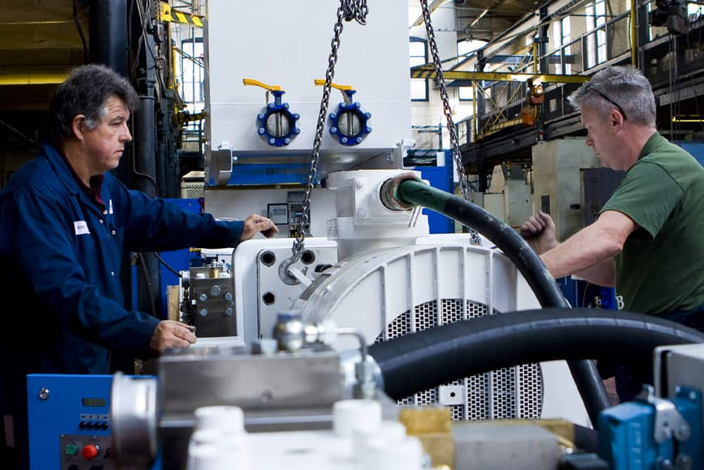
WKL Class High-Pressure Pump Installation
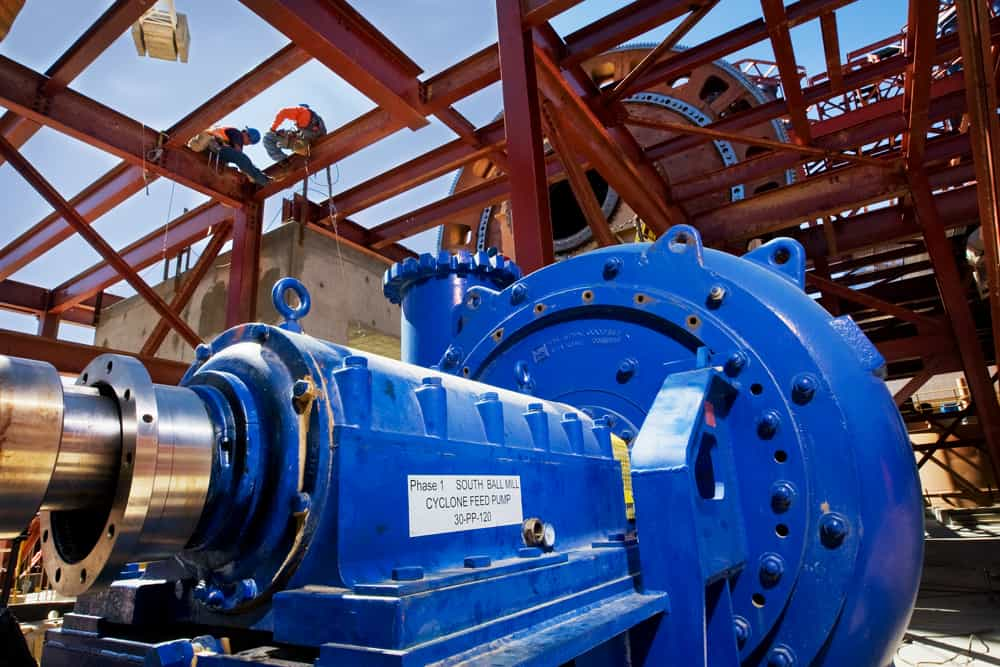
In this section, the way of installation of the high-pressure pumps in the most famous class WKL will be explained, as well as how to take them apart. You need to be familiar with a few key elements before beginning the installation. The actual diameter of the suction pipe cannot be determined from the nominal diameter of the flange because this value does not provide any useful information. The amount of drainage that can be collected at one time is used in the calculation and selection of the suction pipe's diameter. The diameter of the suction pipe should be selected in accordance with the path of the suction pipe as well as the number and dimensions of the connections along this path. This is necessary in order to ensure that a significant drop along this path does not result in an abrupt reduction in the height of the pump's suction. It is strongly suggested that the flow speed of the suction pipe not go any faster than two meters per second. Installing a distinct suction pipe for each pump is recommended as a best practice in most cases. Concurrently, it is preferable for the diameter of the tubes of the net to remain consistent all the way up until the inlet of the final pump. Some additional considerations while installing a proxy pump:
- Avoid abrupt, rapid twists and abrupt changes in cross-sectional area. The inner hut of the sealing washers of the flanges must not impede fluid flow.
- The thermal expansion of the pipes should be controlled so that the pump is not subjected to any additional load.
- Before installing and activating the pump, all tanks, pipes, and connections must be thoroughly cleaned.
- Since welding lava, decay, and other impurities are frequently eliminated over time, it is important to place a strainer in the suction line to prevent their entry.
WKL Class High-Pressure Pump Location
Since the common rail system was first implemented in diesel engines in a special location, the high-pressure fuel pump has developed as a specific WKL class into an essential component of the fuel handling system. In addition to high-pressure pumps, gasoline engines now use a direct injection of fuel, which requires the use of higher pressure. A contemporary gasoline direct injection engine will have a fuel system that combines a low-pressure system with a high-pressure circuit in its fuel delivery system. An electric fuel pump is utilized in the low-pressure circuit in order to withdraw fuel from the tank and transport it to the high-pressure pump. The engine control unit is responsible for regulating the system pressure in the low-pressure circuit as needed, with a maximum of 6.0 bar achievable depending on the system. In the high-pressure circuit, the fuel is pumped by the high-pressure pump through the high-pressure fuel line to the fuel delivery pipe (rail), where it is then given to the cylinder via the electronic injection valve. This occurs in the high-pressure circuit. The engine control unit keeps an eye on the fuel pressure in the high-pressure circuit. Depending on the settings for each component of the system, the engine control unit can adjust the pressure anywhere between 50 and 350 bar. Different high-pressure pumps are able to be fitted in automobiles because of the wide variety of engine designs and manufacturers. In this context, the terms radial piston pumps, axial piston pumps, and linear pumps are used to refer to three separate types of pumps, each of which can be driven by one or more pump parts. Because of the various ways in which a vehicle can be driven, the pump can either be lubricated with fuel or engine oil. 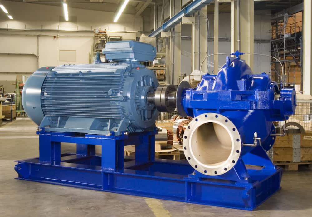
WKL Class High-Pressure Pump Near Me
Where is the nearest gas station to me? Probably you asked this question to yourself. The job of the high-pressure fuel pump, regardless of its specific WKL class, is to provide fuel through the fuel delivery line after first compressing the fuel that is supplied by the fuel pump to the fuel pressure that is required by the injection valve. After this, the fuel is delivered. Because of the high-pressure pump's mechanical connection to the camshaft, the flow rate of the pump is directly proportional to the rotational speed of the engine. The engine control unit includes both a pressure sensor and a flow control valve that is put on the pump. The pressure sensor is used to monitor the fuel pressure, and the flow control valve is used to manage it. The high-pressure pump is linked in a straightforward fashion to the fuel pressure regulator. The performance of the high-pressure pump is regulated as a result of its measuring the supply of the high-pressure pump. Because of this demand-based management, the pump only generates the amount of high pressure that is truly necessary to accommodate the present set of operating conditions. Since liquid water is incompressible, pumping systems must be able to absorb energy un the form of tension or pressure to increase pressure and transfer fluid. Pressurized sources can store and return water at a certain pressure. To minimize excessive turning on and off of the pumps, the shock absorber tank's volume should be bigger than the minimum required to maintain pressure. In low consumption or to manage fluctuations, they pressurize the supply of water. If additional water is needed, the pump supplies it and the tank is refilled. The water pump's sources, pressure level, automated switch, and five-way are connected. 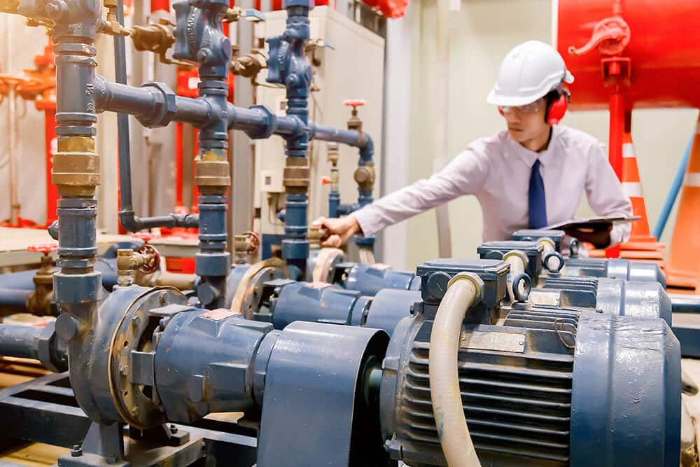
WKL Class High-Pressure Pump Service INC
Multistage vertical and horizontal of the WKL class pumps are the components of high-pressure pumps that are most likely to experience damage and wear and need to service INC, both in general and under the conditions of issues in the structure of the pump. Damage to the structure of floor pumps can be caused by a variety of factors, including dry working, poor alignment, staying under load, employing a pump that is not suitable for the fluid being pumped, as well as thermal and electrical shocks. At this point, we are going to analyze the typical issues and flaws that crop up during the operation of floor pumps, both overall and in the several steps that make up the process.
- There is a lot of noise coming from the floor pump. Check the water level in the pump.
- Examine the pump's intake and outlet ports to ensure that they are clean and unobstructed.
- Make sure that the bearings in the electric motor pump are in working order.
- Check the flooring of the pumps as well as the positioning of the propellers and diffusers (after the repair process).
- Check to see what kind of condition the coupling is in.
- The pump does not have the essential irrigation
- The pump's propeller and diffusers should be inspected, and if they are broken or worn, they should be replaced.
- In addition to the bearings and the electric motor's circuit, the winding of the electric motor should also undergo a visual inspection to determine whether or not it is healthy.
- Examine both the pump's inlet and its outlet for any signs of clogging or blockage.
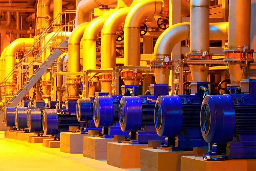
- The pump has a significant amount of vibration;
- Check the pump's alignment.
- It is important to inspect the bearings in the electric motor and the pump.
- Make sure that the pipes and the pump are connected properly (if necessary, use anti-seismic rubber and tighten the flanges correctly with the right torque).
- Check the coupling on the pump.

0
0