The supervision of flow and level factors and overall control of high-pressure pumps in the WKL class in order to maintain the level of the target ball is the responsibility of the pump controller. The controller is one of the most important components of the pump, and its operation can be as simple as turning it on and off, or it may include more complex manipulation of pump speed, output pressure, etc. A great number of pump controllers come equipped with functionalities such as rate indication, collector, data logger, and graph logger. There are additional products available that can manage the level of pressure or the amount of pressure. Processes can have liquids or solids that need to be monitored, regulated, and controlled by using liquid level controllers. Pressure controllers accept input from pressure sensors, transmitters, pressure gauges, and other devices. The pressure is then adjusted and controlled by the pump controller in order to either maintain the desired level or reach it. 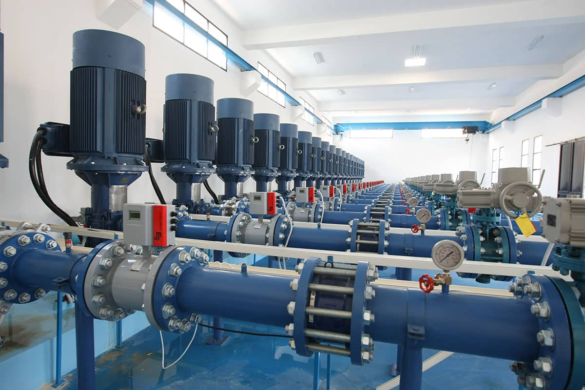 Some pump controllers take the form of printed circuit boards, sometimes known as PCBs, and link directly to the backplane of the computer. Others mount to racks and embed hardware like rails, flanges, or tongues; mount to conventional DIN rails; or attach plates or screws to the chassis, walls, cabinets, or cabinets. Pump controllers are also available for use with entire enclosures or cabinets, which can be placed on a desktop or floor, with integrated user interfaces. The pump controller's specifications include the number of inputs, outputs, input type, output type, and the number of zones (if applicable). The total number of signals supplied to the control unit is equal to the number of inputs. The entire number of outputs used to control, compensate or rectify the process is equal to the number of outputs. Current (DC) voltage, current loop, resistance or potentiometer analog signal, frequency input, and switch or relay input are examples of input types. Types of output include analog voltage, current loop, output from a switch or relay, and pulse or frequency.
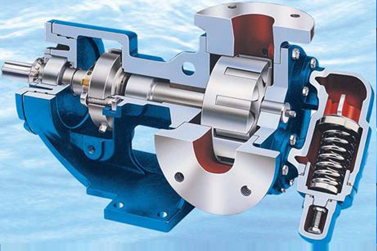
WKL Class High-Pressure Pump Ball
The proper selection of pump control valves in the high-pressure WKL class is a crucial component in the design of pumping and sewage systems. The major goal of these valves is to avoid backflow into the ball when the pump is not working. In order to prevent water hammer or surges, the pump control valve needs to have the ability to carefully and slowly control changes in the fluid's velocity. This is especially important in pipelines that are very lengthy. One more benefit of the valves that is frequently disregarded is their capacity to cut down on energy use. It is estimated that the cost of pumping water and overcoming pressure and friction losses accounts for approximately 80 percent of the total cost incurred by water and wastewater treatment plants. By selecting the appropriate valves, one can obtain significant reductions in the pressure drop across those valves, so conserving energy. There are a few distinct varieties of pump control valves, the most common of which are butterfly valves, ball valves, and eccentric valves. 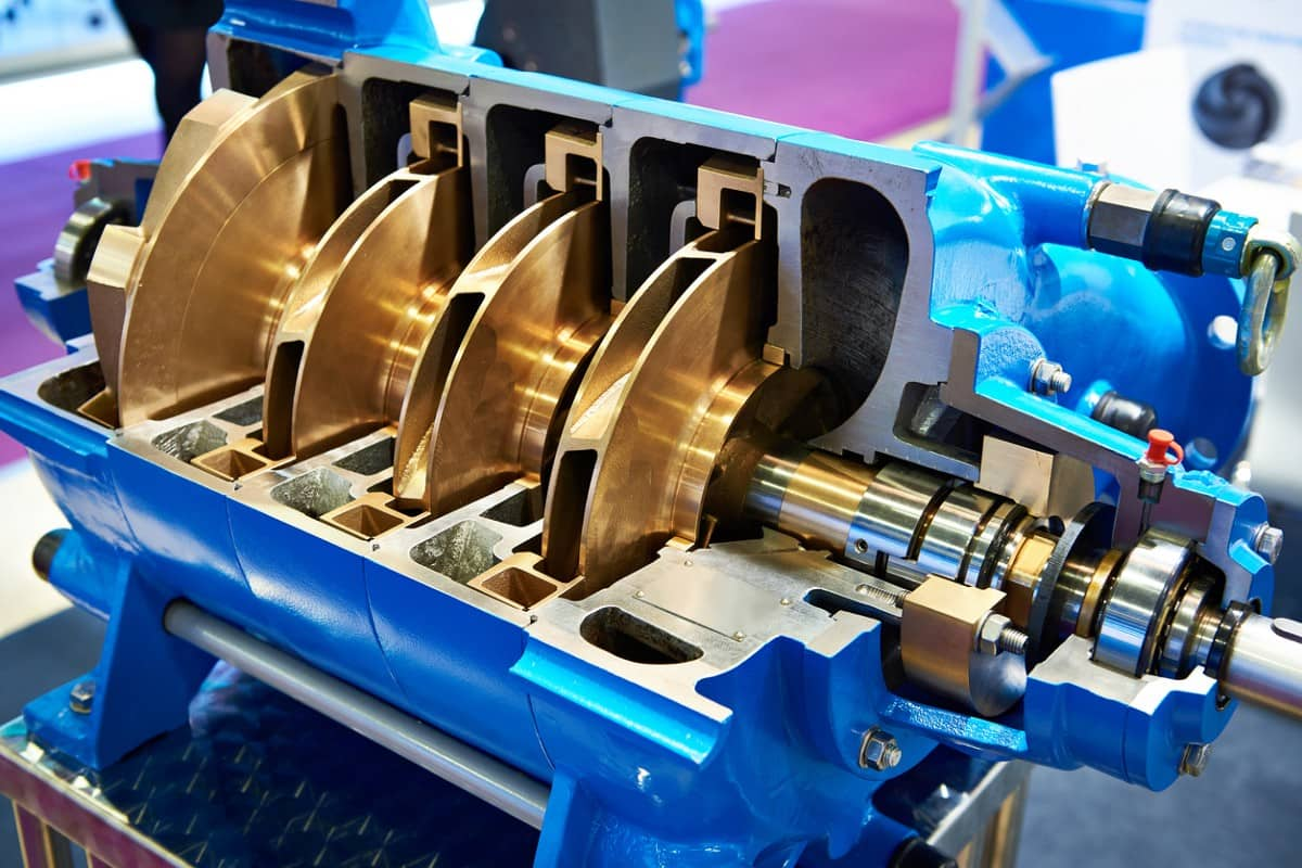 These valves are all electrically connected to the pump control circuit in order to provide a synchronization function with the pump and thereby control the flow rate of fluid in a more methodical manner. for a long time (for example, sixty to three hundred seconds) in order to prevent surges in electrical conduits, pipes, and distribution systems. When choosing a pump control valve, performance, a low-pressure drop, and flow characteristics are all important factors to take into consideration. As a result, the AWWA C507 ball valve will be discussed in this article, along with the benefits that come with employing it for pumping applications. The OmniSite Crystal Ball is a self-contained single-channel set-point controller and web-based emergency alert system that provides remote monitoring and operation of any type of equipment without the need for dedicated phone lines or radio systems.
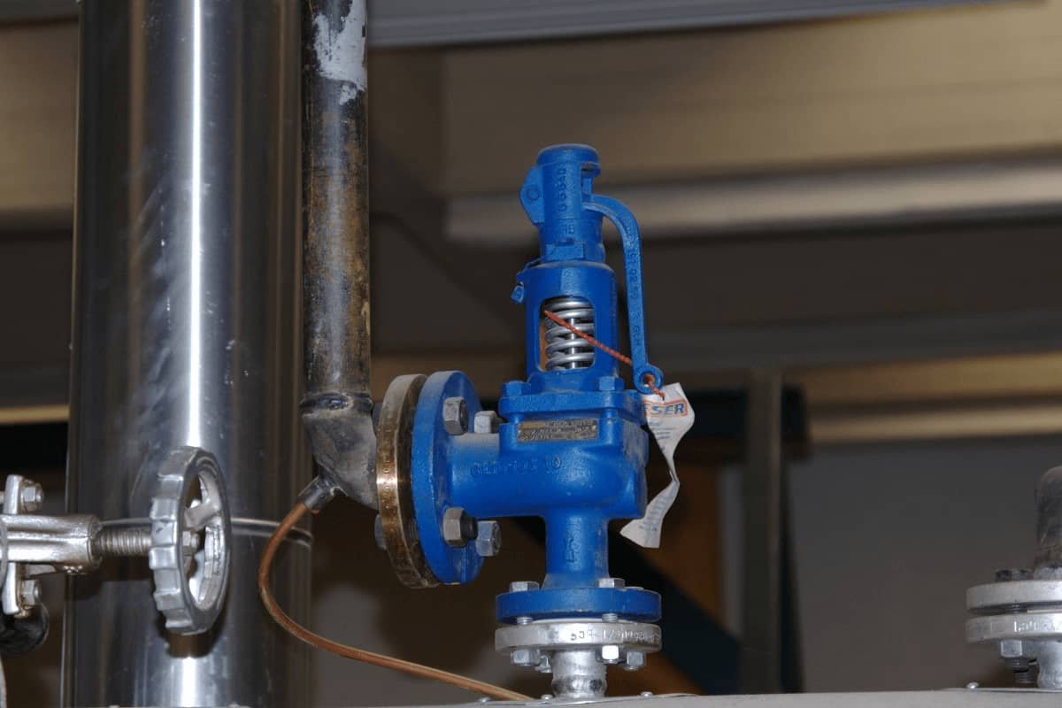
WKL Class High-Pressure Pump Controller
Pumps and their controllers are essential components of the technologies used today. In the WKL class, the primary purpose of high-pressure pumps is to either cool a variety of systems or transport fluids. As a result, your needs and preferences for pump control are somewhat varied. Control for smaller pumps must be fundamentally different from control for larger pumps since smaller pumps have less power. Even the procedure for starting and stopping the pump might be rather varied for various sizes of pumps. This calls for the utilization of an entirely separate set of pump control characteristics. The pace of the pump and, consequently, the pump's output are both within the controller's control. Different types of sensors, such as flowmeters and level sensors, are responsible for providing the input variables. Following the activation of the pump control unit by this information, the speed of the pump is then adjusted to the most effective level. 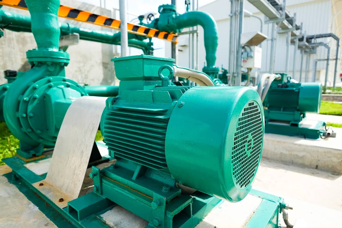 Utilizing an inverter, converter, or frequency converter is a simple and effective method for controlling the pump. Controlling the amplitude or adjusting the frequency can be used to alter the speed at which the object is rotating. The control operates very effectively and swiftly thanks to the frequency converter, which is once more reflected in the good controllability of the pumping station. A frequency converter is an inverter that generates variable-frequency single-phase or multi-phase alternating current with a voltage output. This output value is utilized to control and operate a three-phase motor. The inverter uses diodes and filter capacitors as intermediary volumes to rectify each inverter phase, followed by inversion via a programmable transistor. Controlling the integrated circuit allows for the frequency and voltage/current of each phase's output to be modified. The pump control drive motor may be mounted on either the pump or the tank. The control system cabinet's IP rating must protect against dust, high water temperatures, electromagnetic interference, and mechanical interference.
WKL Class High-Pressure Pump Components
In WKL class pumps, those components that operate at high voltages can be utilized in the construction of solutions that are highly optimized in terms of weight and area. Most of the time, when people talk about "high pressure," they are referring to pressure levels that are higher than 450 bar. The majority of the time, high pressure is necessary for circumstances in which cumbersome objects need to be moved or in which powerful actions need to be carried out precisely in confined areas. For instance, if it is anticipated that the system may encounter pressure peaks of up to 1000 bar, selecting components rated for higher pressure will ensure that the system is able to function normally under these conditions. Normal hydraulic systems are made up of a variety of components, not all of which are designed to withstand high pressure. Pumping system components include:
- Water source
- Water pump
- Filters or screens
- Hoses or water lines
- Valve
- Head or sprinklers
- Pressure sensor
- Pressure release tank
- Controller
- Pump start relay
 There is neither a mechanical pilot valve nor a lengthy internal pilot route, in contrast to the vast majority of other air-operated pumps.
- Reliability in addition to unfavorable effects
- pumping velocity
- Pneumatic drive part
The only moving parts in this pump are the air piston and the bicycle pulley. Keep the pump from freezing over by doing the following:
- Make use of an air circulation valve designed for mild duty.
- Low airspeeds with a high number of airflow coils.
It only takes a few minutes to replace high-pressure seals, and there is no need to disassemble the pneumatic drive section. Additionally, seats can be changed out in a matter of minutes. There will be as little downtime as possible. The pump can operate with either nitrogen or compressed air and has a maximum pressure of 7 bar (100 psi). 
WKL Class High-Pressure Pump Line
There are many different applications for high-pressure pumps in the industrial production line. Pumps exist in different classes and different fields and are responsible for pumping oil, water, and other liquids in order to create high pressure. Compressed air with pressures ranging from 1 to 10 bars is required for the operation of these pumps. These instructions ensure that high-pressure air-operated pumps are used in a manner that is both safe and effective. It is imperative that this directive, which is a component of the high-pressure pump, be maintained in its direct direction. The fuel injection line must be able to move fuel from the high-pressure pump to the internal combustion engine without letting the pressure drop, blocking the flow of fuel, or stopping the fuel injection parts from working. Compression takes place while the huge pressures on the fuel are safely and effectively transmitted without any loss.
- It resists breaking despite being subjected to the high acceleration and vibration levels produced by internal combustion engines, as well as exhibits resistance to vibrations.
- Ensures the cleanliness of components down to the micron range, which eliminates the risk of failure for precision-engineered and delicate fuel injection components.
- Even after a long time of use, you can be sure that the fuel system will still be airtight.
- Always able to withstand the effects of the environment without suffering any functional deterioration and is resistant to corrosion as well.
 WKL Class High-Pressure Pump Motor When compared to pump technologies that use medium compression, high-pressure motors are able to do more tasks while taking up less space. High-pressure technology in WKL class pumps can be utilized to improve the performance of mobile and stationary hydraulic systems by reducing the size of the package, increasing the digging torque, and decreasing the cost of the system. In the end, this indicates that mobile equipment such as skid steer loaders (SSL and CTL), earthmoving equipment, crushers and mixers, material handling, and other types of mobile equipment will be able to perform additional tasks while simultaneously producing fewer emissions and consuming less fuel. The shift from medium pressure to high-pressure models is typically caused by three factors:
- Size of equipment: As machinery gets more compact and adaptable, products with higher pressure can reach the same capacity in a smaller space.
- Applications, where more powerful engines provide more productive or efficient machinery, contribute to greater production.
- Future Compatibility: Compatibility with upcoming updates and modifications
 The decision of the sort of engine to use is heavily influenced by a wide variety of different elements. Because of the numerous benefits that the most recent high-pressure actuator technology has to offer, this type of actuator is the one that should be selected for the vast majority of hydraulic systems. High-pressure engines are between 1.5 and 2 inches shorter than their medium-pressure counterparts, making them more space efficient. Higher pressure engines require less cooling area due to their enhanced efficiency in the mechanical department. Engines with a higher compression ratio generate less heat, therefore they use less fuel throughout the course of the equipment's lifetime. When designing a machine, weight is an important factor to take into account because it can frequently have an effect on a number of performance factors, such as the required lift capacity, ground pressure, and traction needs. Being overweight results in wasted fuel, the need for stronger machine construction, and the frequent occupation of a significant amount of space.
WKL Class High-Pressure Pump Mystery Filters
There is a purpose for the existence of so-called mystery filters, and that reason is a good one. When you remove these filters from your high-pressure pump in WKL class, you run the risk of severely reducing its lifespan and, in some instances, even bringing it to an end entirely. In earlier iterations of HPDI pumps, there were three HPDI diffusion filters included in the pump. One is located on the actual pump body, one on the pressure regulator, and one elsewhere. The new pumps from HPDI come equipped with two "fuzzy filters" in each pump. Two single pumps and four double pumps are included in that total. Both can be found inside the body of the pump. When the obscured HPDI filter is removed from the pressure regulator, it has the potential to leave debris on the seat of the pressure regulator.  This will result in the pump not being able to build up pressure since it will empty. A very small amount of space, measured in thousandths of an inch, separates the regulator shaft and the seat body. If debris is present in this area, it can cause the regulator to become either stuck in the open position (in which case the pump will not produce pressure), or stuck in the closed position (in which case the pump will become stuck). An excessive amount of pressure. The same filter is maintained by a number of pumps. The filter, which has a barrier that resembles a sieve and prevents debris and air from entering while still allowing water to flow through, receives filth that has made its way through the water pipes. For instance, if you are stressed, you need to make sure the water pipes are clean.

0
0