In most cases, screw pumps are fabricated from standard mild steel and include a unique epoxy finish. It is necessary to choose an appropriate coating system for each individual application. In addition to this, the shaft material is capable of fabricating any size screw pump out of stainless steel. Positive displacement pumps are a type of pump that may be broken down into subcategories, and one of those subcategories is screw pumps. A pumping motion is carried out along the axis of the spindle by it. Two primary components make up the entirety of a set. The pump assembly with the drive motor (the main motor). A pump drive screw that is attached to a motor's shaft receives the necessary rotational motion from the motor. This, in conjunction with the limited space present between each tooth, results in the creation of suction pressure. Within the same range of speeds, it has a higher capacity for sucking air and requires less maintenance. Additionally, it is often regarded as the most dependable pump for a variety of applications. Screw pumps are well-known for their low levels of turbulence and vibration, as well as their ease of use with viscous fluids. It does not allow for the formation of air pockets inside the fluid, hence reducing the amount of noise produced during operation. 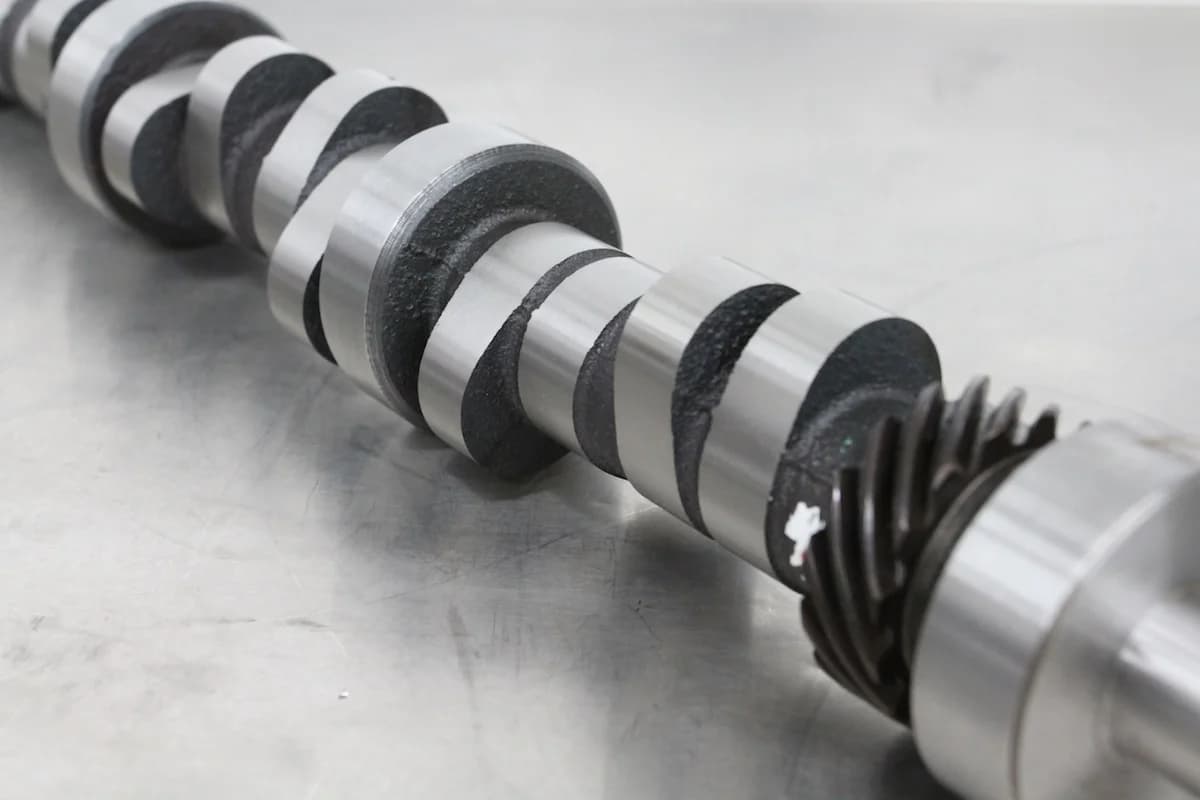 Screw pumps are an excellent choice for a wide variety of applications, including lubrication, fuel transfer, high-pressure fuel injection, and participation in hydraulic power. Because of this, it is suited for a diverse range of applications within the induction sector of the industrial sector. Marine industry, oil refineries, food processing, chemical facilities, heavy industry controlled by hydraulic power, power plants, and other similar industries. The primary purpose of ship screw pumps is to move fuel oil from the double-bottom tank to the jug, and this is accomplished by turning a screw. There is a wide variety of forms and styles of screw pumps, the most popular of which are either three or two screw pumps. The liquid medium is entrapped in the tight space between the teeth, which then propels it forward. A pump that just has one screw is referred to as a single screw pump. A cellular twin screw pump is what you'll get when you look up "twin screw pump." Multi-screw pumps are referred to as such because they have two or more screws. No matter the variances in the design or the percentage share in general application. The following is a list of the primary components that may be found in screw pumps: drive screws, driven screws, intake ports, discharge ports, swivel joints, pins, fixed joints, ball bearings, circular clips, drive shafts, and timing gears.
- Driver Screw
One of the components of a screw pump that rotates is called a screw drive. Because of this, the liquid can be pumped at a rate that is constant in terms of its volumetric output at every return point.  On one side is connected a driving shaft, while on the other side is attached a timing gear. It revolves with a close clearance to the drive screw in order to move the fluid axially ahead along the angle of rotation as it rotates. A threaded shaft constructed of high-strength steel is what makes up the majority of a lead screw. The screw drive in a screw pump is responsible for driving the drive screw by way of an intermediate link known as the timing gear. This is the primary function of the screw drive. A modest shearing effect is helped to be created by having a slight axial movement of the screw, as well as a short clearance with the driven screw. This further enhances the longevity of the pump by preventing circumstances such as the emulsification of the fluid medium that occurs when the water becomes contaminated, as well as unfavorable impacts on other linked pieces of gear.
- Driven Screw
The screw drive and this component share the same material composition. The action of the movement being transferred by the synchronous gear causes the drive screw to revolve along its axis so that it may do its job. In contrast to a lead screw, it has a clearance area that remains constant while rotating in the opposite direction. Because of this, water and other liquid media are contained in a confined area of space. The clearance area does not shift in this case since the two screw pins rotate in different directions from one another. By flowing the fluid axially along the rotation angle, it produces an output that is completely devoid of vibrations.  It ensures that there is hydraulic equilibrium along the axis that runs through the center of the pump. Both the driver and the driven screw shaft have a threading pattern that is in the opposite direction. That is, the screw that is being screwed in will be left-handed if the lead screw is right-handed, and vice versa if the lead screw is right-handed. In addition, the lead screw requires a noticeably less amount of time to operate when the operating circumstances are optimal. a fraction of one-twelfth to one-fourteenth of the total torque applied to the pilot screw.
- Timing Gear
Both the lead screw, which is the male rotor, and the driven screw, which is the female rotor, work with extremely close tolerances. There is never a time when communication is impossible. This kind of contact can erode the edges of the screw, which will considerably lower the outflow pressure. If this is allowed to continue unchecked, the pump will not only become uneconomical, but it will also become much less efficient . On the other hand, this can sometimes prohibit the teeth from interlocking with one another. Timing gears are therefore put on screw pumps in order to control the occurrence of such events. The timing gear will move the driving gear in the manner that will be described below. There is no contact between the male and female rotors' metal components. In addition to this, we warrant that there will be no encounters of this kind. Even if the pump is empty for a very brief period of time. Design of a three-screw pump that lacks a timing gear. While the two screws on the outside are inactive, the central driving screw is responsible for producing axial fluid movement. 
- Suction & Discharge Port
The suction and discharge ports of screw pumps are distinct from one another because the fluid travels axially along the screw towards the discharge port. The following describes how the input and output are designed. It contains sufficient liquid fluid for use once the pump has been turned off. This contributes to the initial liquid medium being delivered to the pump. It is able to avoid dry running for brief periods of time when the suction hose is empty or dry. A portion of the vacuum is drawn through the suction port. The difference in pressure that exists between the pump's suction port and its inlet is what gives rise to it. This supplies the fluid medium with the necessary thrust that it requires. to fit into a variety of tight places while passing through thin screw apertures. On the other hand, there is an extremely large amount of pressure at the outlet. In all and all settings, the pump is able to push more fluid. As a result, the vortex that is created on the discharge side of the pump is almost always larger than the one that is created on the suction side.
- Relief Valve / Recirculation Line
Even when the outlet is closed, screw pumps continue to produce pressure since they are a subset of positive displacement pumps. This could have extremely negative repercussions.  This includes the pump and any linked apparatus being destroyed, which results in the operator being hurt. As a result, it imparts a sense of security not just to the pump but also to the machine to which it is linked and to the person operating the pump. This particular positive displacement pump, like all others of its kind, has a pressure release valve built into it. Recirculation of the output fluid is an additional popular approach used to bring the pressure back down to normal levels. A recirculation valve can be utilized to accomplish this goal. A portion of the liquid from the outlet flows back into the system via the internal tube and into the suction port. These safety valves have an automatic flow control mechanism that is integrated into the design of many different types of contemporary pumps. Always keep the outlet pressure and flow at the same level. This also lowers the beginning torque of the screw pack, which, as a result, results in the output being pressured in the other direction.