Pump Multi Parts Purchase Price + User Guide
In this article we are going to explain about 6 stage centrifugal pump multi parts and industrial applications of these kinds of pumps.
Pump multi parts nozzle
Keep reading.
In pump systems, there are numerous approaches to satisfy high head requirements.
Which one, nevertheless, is ideal for your process? He uses two different design approaches, one employing a multistage centrifugal pump and the other several centrifugal pumps connected in series.
This essay contrasts them.
The most crucial factors to consider when deciding whether a project will use series or multistage centrifugal pumps are pump performance, system operation, and cost.
Compare the results of each approach in these areas.
Efficiency
Usually, multi-stage pumps prevail in this conflict.
For maximum performance and efficiency, these pumps have small impeller diameters and restricted clearances.
Additionally, fewer motor horsepower should be needed.
There is only one motor, hence less energy is used in this setup.
Space
Because they are positioned vertically, multi-stage pumps can conserve space on the floor.
Single-stage pumps can be put vertically, but when placed next to one another, they will obstruct space in both the vertical and horizontal directions.
Stress adaptability
He needs a VFD to manage the multistage pump and control the pressure rise, assuming steady flow.
The "manually" generated pressure can be decreased by connecting several centrifugal pumps in series and using the Isolate/Bypass option to divert flow from one or more of the pumps.
Concrete
Centrifugal pumps with multiple stages can't move solids.
When the process fluid contains debris or considerable particles, multi-stage pumps are not a good option.
Maintenance
Single-stage pumps feature fewer parts and stages, depending on the size and quality of the pump, making them simpler to repair.
Pump multi parts for stove
Additionally, with several pumps in the system, perhaps there are enough operational spares or technical spares available to maintain the process.
But keep in mind that you will require more preventative maintenance the more pumps you have.
Price
By evaluating elements including equipment, plumbing, labor, energy use, and maintenance, this category might go either way depending on the type of pump and application chosen.
A straightforward application, typically in several phases, is advised for clean liquids.
Choose
With a smaller impeller diameter and narrower impeller clearance, multi-stage centrifugal pumps are more efficient.
Low energy and a tiny motor size can produce high pressure.
It has a more compact footprint.
Low-end suction centrifugal pumps can cost less upfront but run more expensively over time.
Solids cannot be handled by it, and all sorts of differential pressure call for a VFD.
The biggest warning, though, might be that you run the risk of drowning if the pump breaks.
A single-stage centrifugal pump connected in series with an isolation/bypass valve enables manual pressure control and system flexibility.
When modest pressure build-up is needed, for instance, pipes might direct flow from a pump.
In the event of a pump failure, this enables the system to run partially or with a backup pump.
These pumps might not be effective, though, depending on the type of impeller.
The size of the motors, not to mention the quantity needed, may exceed polyphase.
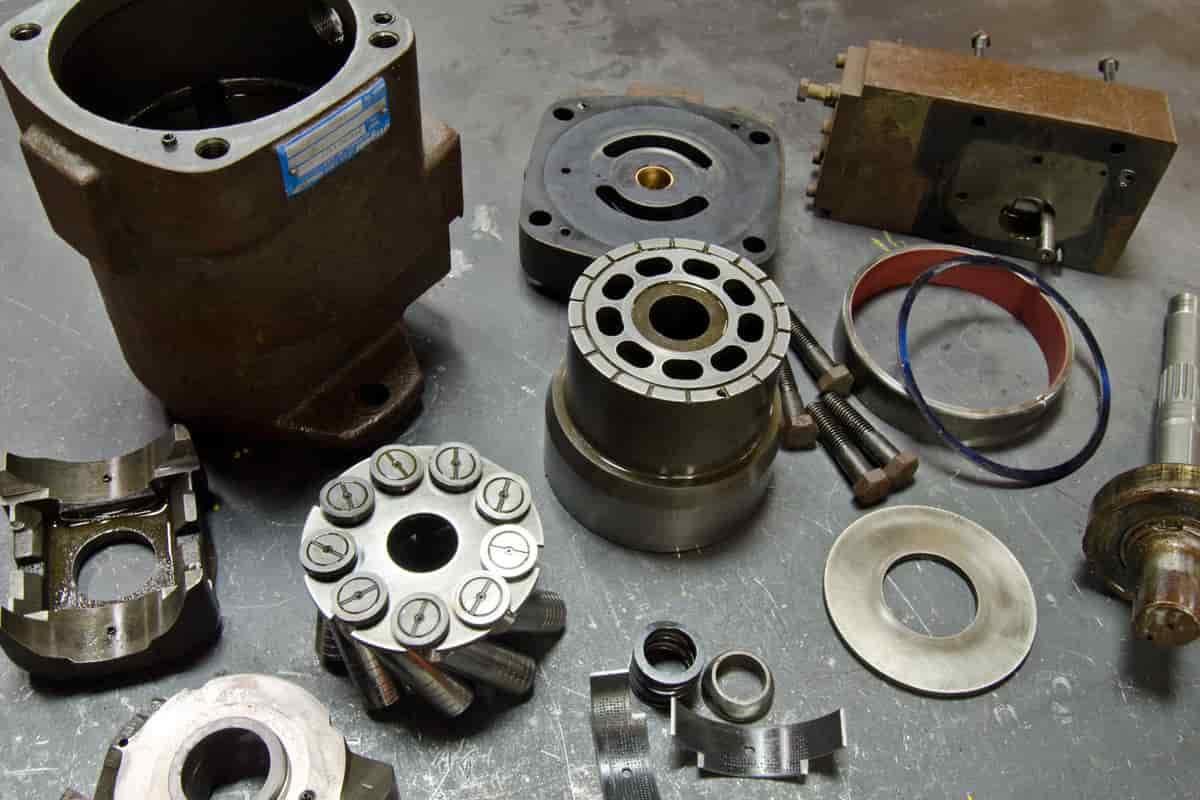
Centrifugal Pump Parts
Almost all centrifugal pump types share a few parts in common.
These elements include:
Catalyst
Impact caused by a volute or diffuser-style cover shaft sleeve
Roof structure
Wet end and mechanical end are two categories for these components.
There are parts in the pump's wet end that have an impact on how hydraulically efficient it is.
The mechanical end is made up of components that allow the shaft to rotate, seal the casing through which the shaft passes, and sustain the impeller within it.
The wet end produces flow and pressure as a result of this.
We typically
The casing and the impeller, the two major components of a pump, have already been covered.
Consequently, we don't stay long here.
Simply put, the impeller accelerates the water by spinning quickly.
When the impeller is inside the casing, pressure is produced as a result of the impeller's rotational velocity.
See our article on the subject for additional details regarding this procedure.
End mechanical
Pump shafts, shaft sleeves, sealing components, and bearings are examples of mechanical parts of pumps.
Motor shaft
The shaft is connected to the impeller.
The shaft is shaped to support the impeller and is often composed of steel or stainless steel.
Shafts need to be meticulously formed.
Undersized shafts can shorten the pump's lifespan by causing shaft failure, increased bearing wear, and increased pump vibrations.
However, a shaft that is overly large can result in an unnecessary increase in the pump's price.
Blade sleeve
The portion of the shaft that is covered by the shaft sleeve on the majority of pumps is below the sealing structure.
A shaft sleeve is a metal sleeve that slides or screws onto the shaft.
It is typically made of bronze or stainless steel.
To protect the shaft and place the impeller on it correctly, shaft sleeves are employed.
Roof structure
The stuffing box refers to the location where the shaft enters the casing.
The space between the shaft and the stuffing box wall needs to be sealed using a sealing device.
In this component, sealing can be accomplished via packing or a mechanical seal.
How do mechanical seals function?
The cost, performance, and design of mechanical seals vary.
 A rotating surface, a fixed surface, a gland, and a spring make up the simplest seal.
The glands are bolted directly to the stuffing box's front, placed around the pump shaft, and fastened to the pump casing.
A gland around the pump shaft seals and fastens a stationary sealing ring, also known as a mating ring.
An elastomeric element seals a rotating seal ring, also known as a primary ring, to the shaft and presses it up against a matching ring that is held in place by a spring.
The spring pushes against a retention clip or collar that is fixed to the pump shaft in order to apply pressure to the primary ring as it rotates.
The only method for fluid to escape the stuffing box is through the rings, which are joined by a spring.
The stationary mating ring is sealed in the gland, and the revolving main ring is sealed in the shaft.
The revolving surface revolves with regard to a fixed surface while the pump shaft rotates.
The heat produced by the rotation of the seal faces pumps a tiny amount of fluid between the faces, where it is then evaporated.
This tiny amount of liquid is enough to lubricate and cool the sealing surfaces.
Any leakage between the shaft and the stuffing box wall will be completely removed as long as the sealing surfaces are spotless, smooth, and lubricated.
Pump sleeve
The bearing array is the final component of the mechanical end.
Typically, ball-type rolling bearings are included as standard equipment with centrifugal pumps.
These bearings, which are lubricated with grease or oil, are the same ones used in electric motors, roller skates, and cars, among other things.
The pump shaft is supported and held in place by bearings that are sized to ensure an acceptable service life and is designed to manage all loads brought on by the moving impeller.
Design engineers and end users are frequently particularly interested in specifics about the design of bearing arrangements because bearing failure is one of the most frequent causes of pump downtime.
Pump specialists might devote a lot of effort to studying the details of the pump bearing systems they use.
A rotating surface, a fixed surface, a gland, and a spring make up the simplest seal.
The glands are bolted directly to the stuffing box's front, placed around the pump shaft, and fastened to the pump casing.
A gland around the pump shaft seals and fastens a stationary sealing ring, also known as a mating ring.
An elastomeric element seals a rotating seal ring, also known as a primary ring, to the shaft and presses it up against a matching ring that is held in place by a spring.
The spring pushes against a retention clip or collar that is fixed to the pump shaft in order to apply pressure to the primary ring as it rotates.
The only method for fluid to escape the stuffing box is through the rings, which are joined by a spring.
The stationary mating ring is sealed in the gland, and the revolving main ring is sealed in the shaft.
The revolving surface revolves with regard to a fixed surface while the pump shaft rotates.
The heat produced by the rotation of the seal faces pumps a tiny amount of fluid between the faces, where it is then evaporated.
This tiny amount of liquid is enough to lubricate and cool the sealing surfaces.
Any leakage between the shaft and the stuffing box wall will be completely removed as long as the sealing surfaces are spotless, smooth, and lubricated.
Pump sleeve
The bearing array is the final component of the mechanical end.
Typically, ball-type rolling bearings are included as standard equipment with centrifugal pumps.
These bearings, which are lubricated with grease or oil, are the same ones used in electric motors, roller skates, and cars, among other things.
The pump shaft is supported and held in place by bearings that are sized to ensure an acceptable service life and is designed to manage all loads brought on by the moving impeller.
Design engineers and end users are frequently particularly interested in specifics about the design of bearing arrangements because bearing failure is one of the most frequent causes of pump downtime.
Pump specialists might devote a lot of effort to studying the details of the pump bearing systems they use.

6 Stage Centrifugal Pump Applications
What applications exist for 6 stage centrifugal pump types? Short response.
These pumps can be used in a variety of applications depending on the type of pump.
Centrifugal pumps with several stages are frequently used in a wide range of applications.
Engineers find them to be a great option for a variety of uses because of their high energy efficiency, ability to deliver a variable range of flow rates, and head heights.
A multistage centrifugal pump is what?
Two or more impellers are used in the construction of multistage centrifugal pumps.
Depending on the configuration, the rotors can be installed on either the same shaft or a different shaft.
In order to achieve a higher outflow pressure, rotors can also be joined in series.
However, they are frequently connected in parallel when huge capacities are required.
Centrifugal pumps with many stages are used in a single housing and produce a lot of pressure on the shaft.
Compared to pumps with a single impeller, this is cheaper.
Channels in the pump housing function as a component of the pump's structure by guiding one impeller's discharge to another's suction.
Water enters the pump and flows from left to right through a succession of rotor combinations.
As a result of the water spiraling around one rotor's helix, suction is produced in the other rotor.
These pumps typically come in a single stage.
Centrifugal pumps with multiple stages work quite effectively.
Axial pressure forces can be adjusted for multi-stage centrifugal pumps by balancing blades positioned behind the impeller.
To absorb residual forces, high strength ball bearings are utilized on the drive side and angular ball bearings are used on the drive side.
Two outer bearings, which are seal pressure balance lines that release pressure from the discharge side seal to the suction side, are included with multi-stage centrifugal pumps.
Even when the pump is working at high pressures, this special design enables the adoption of more affordable seal combinations.
Depending on its capacity and intended use, pumps are available in a range of sizes.
Pump multi fuel stove
Small multi-stage centrifugal pumps are appropriate for autoclaves, hydrocarbons, boiler water supply, autoclaves, water pipes, irrigation, agriculture, and conveying clean liquids in light soils.
The multistage centrifugal pump's operation
The discharge pressure at the exit of the pump increases with the number of stages it has.
After each stage is added, these pumps excel at producing high pressures, but the flow range is always consistent at a fixed speed.
Within a single stage housing, each stage consists of a rotor, diffuser, and directional return blades (typically attached to the diffuser).
The type of the impeller and the peripheral speed can be used to roughly change the pressure head of a single-stage centrifugal pump.
A big impeller diameter will lead to a very low specific speed and uneconomical efficiency if the operating conditions demand a constant rotating speed.
Therefore, mounting several stages in series is a cost-effective way to increase head.
A multistage pump's flow rate is unaffected by changing the number of stages to a constant amplitude and speed, but the power input and head are increased proportionately to the number of stages.
Fluid passes through numerous impellers mounted in succession in a multi-stage pump.
Pump multi parts supply
The suction line pressure is the pressure at which fluid enters the first chamber (or stage) and the pressure at which it leaves.
The fluid reaches the second stage, where the pressure increases once further, after leaving the first one.
The pump series selection chart's higher pressure ranges can be reached economically by using multi-stage pumps.
The enhanced rotor sensitivity to internal or exterior vibrations is the only disadvantage of having numerous stages, though.
An illustration of a pump with the same style of multi-stage casing is a pair of ring section pumps.
This kind of pump is frequently used in industrial settings that need for high pressure, such as boiler feed pumps in power plants.
Multistage centrifugal pumps don't necessarily need to have all of its stages mounted simultaneously.
By placing back-to-pack in pairs or groups, axial force balance can be enhanced.
A pipeline pump is a typical illustration.
Regardless of the number of stages, the first stage is positioned in front of an inlet housing with an axial or radial intake nozzle, and the last stage is positioned inside an outlet housing with a balancing device and a shaft seal.
The only parts that need to be adjusted in the required number of steps are the pump shaft, tie rod, and base plate.
How useful is this article to you?
Average Score
5
/
Number of votes:
1