Buy all kinds of wire ethernet cable + price
The wire and cable are basically divided into two groups, the stranded types or the solid conductors. It is amazing how much the properties of each type of conductor can change the properties of the Ethernet wires and cables.
wire ethernet cable
The Institute of Electrical and Electronics Engineers (IEEE) came out with a new set of standards towards the tail end of 1990 that introduced data-capable twisted-pair cable that could be used in 10 Mbps Ethernet networks.
This new 10Base-T standard established a star topology built around a central "data traffic controller" (a hub or a switch), to which each workstation in a Local Area Network (LAN) could be connected independently via a single dedicated UTP (Unshielded Twisted Pair) cable.
Previously used networking systems relied on coaxial cabling and a bus topology. This new standard replaced those older methods with a star topology.
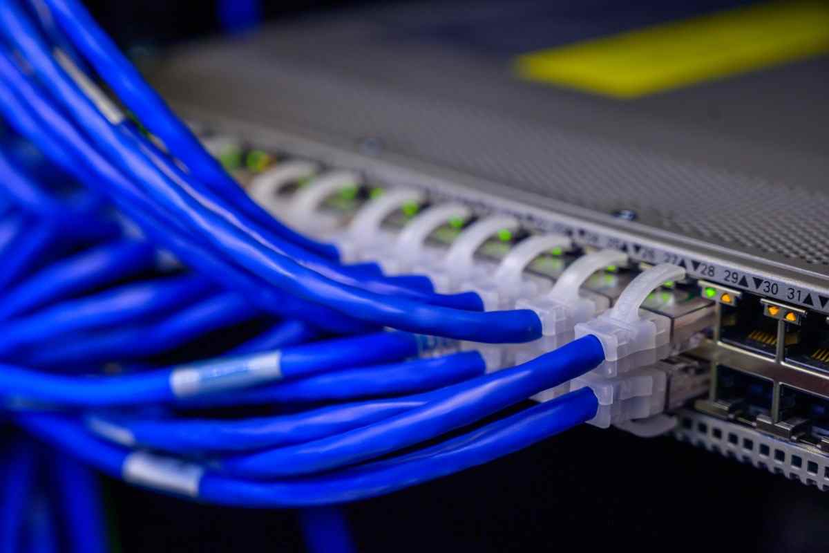 Installing and debugging Ethernet networks became far simpler thanks to the star topology and 10Base-T technology, and the management of these systems became significantly more effective.
Since then, twisted-pair cabling has established itself as the preeminent network cabling scheme, which has contributed to the enormous growth in the use of Ethernet that is still going strong today.
There are now an overwhelming number of different types of twisted-pair cables that can be purchased.
These cables correspond to an overwhelming number of different standards that detail the configuration and performance specifications that are required to support technologies that have data rates that are getting faster and have wider bandwidths.
The growth of this well-known and well-understood copper medium may be seen in a list of Category-type ("CAT") cables that have been produced to suit these new specifications. 10Base-T was the first protocol to use regular telephone wire as the transmission medium.
Each cable type in turn comes in two flavors, namely as a solid-conductor cable and as a stranded-conductor cable, for CAT-3 cables and higher. These two varieties are solid and stranded, respectively.
Despite the fact that both types within each category are manufactured to meet the same cable configuration and electrical performance specifications.
the different physical properties of the two types impose distinct limitations on the length of cable segments and restrict their application to particular locations within Ethernet systems.
As a consequence of this, the two types of cable are put to quite diverse uses, and their functions are rarely swapped with one another.
These conductors typically include bare copper wires with widths ranging from 22 to 24 AWG, and they are employed in cables that are intended for use in networking applications (American Wire Gauge units, or approximately 0.51 – 0.64 mm).
Category 5e twisted pair (UTP) cables always have nominal conductor diameters of 24 AWG (0.0201 in. or 0.511 mm), but higher-performance cables like Category 6 twisted pair (UTP) cables have larger copper wires of 23 AWG (0.0226 in., or 0.574 mm in diameter).
These larger wires offer greater electrical qualities, which allow them to remain stable over a wider range of frequencies than smaller wires, in addition to being physically stronger and easier to work with.
Because of these features, CAT-6 cables are better suited to new and developing applications that use rapid Ethernet.
Because of their greater diameters, solid conductor cables, in general, have a lower DC resistance as well as a lower susceptibility to high-frequency effects.
This is because of how they are manufactured. Because of these characteristics, solid conductor cables are able to accommodate longer transmission distances and higher data rates than their stranded cable equivalents. This will be demonstrated in the following section.
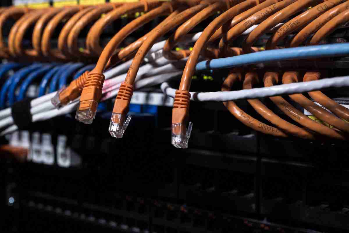
how to wire ethernet cable in house
But the most defining feature of solid Category-type cables is probably the fragility of their conducting wires, which results in an overall inflexibility in the cables.
As we can see from the dimensions presented above, the phrase "bigger" does not apply in this context, since all of these wires are extremely thin when compared to the lengths of the cables and the sizes of the creatures who are responsible for handling them.
Because of their little size, they are not able to withstand an excessive amount of bending or flexing before breaking or experiencing surface imperfections that can alter their ability to conduct electricity.
Because of this, the cables are densely packed inside of a sturdy outer sleeve that is resistant to bending.
As a result, the cables are less flexible and are not well suited for typical everyday use in connecting components of the work area.
Because of their general sturdiness, these cables are best suited for usage within the infrastructure of a system as either horizontal or backbone cabling.
Each individual conductor that is housed within the twisted pairs of a stranded cable is constructed out of a bundle of wire strands that have a lower gauge.
These are organized in such a way that a single wire in the center of the bundle is surrounded by a number of wires (often between 6 and 18).
During the stranding process, the peripheral wires are spirally wound around the primary wire in the middle of the structure. A single conductor is formed by the stranded wires when they are brought together.
This conductor has a diameter that is comparable to that of a conductor in a solid cable, but it has a far smaller conducting area (based on the smaller diameters of the conducting wire strands).
Stranding the wire conductors serves to protect them and also provides stranded cables their flexibility. Stranded cables can bend in many different directions.
The more the number of times that each strand twists around the central conductor for a given length of conductor, the greater the level of protection provided by the cable and the overall degree to which it can bend.
This concept can be measured by looking at the lay of the conductor strands, which is the distance that needs to be traveled by a single wire strand in order for it to wind all the way around the conductor and make one full rotation about its center wire.
To get a better understanding of how this operates, let's start by thinking about a "non stranded conductor." This refers to a conductor in a straight lay cable in which the outside wire strands are not twisted.
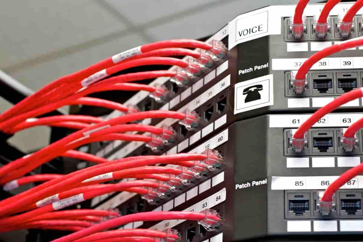
4 wire ethernet cable pinout
When this cable is bent, each individual strand bends virtually exactly the same way it would if it were alone within the cable.
Every time the cable is flexed, the outer strands are free to move about in response to the mechanical stresses that have been induced, which has the ability to alter the conductor arrangement of the cable as well as its transmission qualities.
The center conducting wire is weakened and the cable's lifespan is shortened when it is repeatedly bent in opposite directions without the consistent "cushioning" of the outside wire strands.
When the cable is bent, however, a helical stranding of the wires around the core wire allows all of the individual parts of the stranded conductor to pull toward the cable's center.
This maintains the configuration of all of the elements and prevents them from becoming disorganized.
Their courses around the central conducting wire ensure that the stresses on the individual wires are averaged over the lay length, and that the total stresses are dispersed throughout all of the strands in order to minimize the stresses that are placed on the center conductor.
The wire strands and the central conductor both benefit from more support in proportion to the number of twists that are applied to the wire strands (i.e., the shorter their lay length).
Conductors in stranded Category-type cables, which are typically used for networking and Ethernet applications, are typically constructed of bare copper wires or wires that have been tin-coated.
Before assembling the individual wire strands into a single conductor, the production of tin-coated conductors involves dipping the individual wire strands in a bath of molten tin.
In addition to protecting the conducting surfaces from oxidation, the tin coating makes it simpler to solder the thin wire strands onto patch panels and wall jacks. Additionally, the tin coating protects the individual wire strands from becoming frayed.
 A Remark Regarding Wire Sizes
Copper wire diameter is most frequently specified using American Wire Gauge (AWG) values, which are determined by a conductor's cross-sectional area. AWG stands for American Wire Gauge.
In the American Wire Gauge (AWG) system, the size of a conductor is connected to either the diameter of the conductor if it is a single, solid conductor or the overall diameter of the conductor if it is stranded.
It is common practice to specify stranded conductors by the number of strands and the matching AWG size. For example, a 7/38 stranded conductor has seven wires (6 around 1) and an overall diameter of 38 AWG (0.1524 mm, or 0.018241 in.).
As a result of the conventional method through which these wires were manufactured, bigger AWG size numbers equate to smaller wire diameters (because they had to be drawn more times).
It is interesting to examine the continuous usage of such an outdated method for technologies that develop at such a rapid rate because, as frustrating as this backward specification of size may appear, it is interesting to think about.
Analyses of the Differences in Electrical Properties
As we advance toward more faster Ethernet systems, which require increasingly greater frequencies and data rates, the electrical activity that takes place inside of a copper transmission channel can become a little bit confusing.
To our relief, though, the fundamental electrical qualities that are responsible for these puzzling occurrences have not changed at all.
Attenuation effects are a broad category that encompasses the changes in transmission performance that are observed when switching from one conductor type to another for both solid and stranded conductor cables.
These changes can be noted when moving from one conductor type to the other.
Losses due to Attenuation and Insertion
When a signal is sent from one end of a cable to the other, its intensity, or amplitude, gradually decreases as it travels through the cable.
This phenomenon is known as attenuation. Attenuation, which is measured in decibels (dB), is the same unit that is used to determine the amplitude of sound waves. Attenuation is also known as insertion loss.
When evaluating the attenuation of a cable, dB values that are lower indicate greater performance and less signal loss; also, this indicates that the transmission environment is less "noisy."
Higher dB values are comparable to the loss of voltage that occurs within the cable itself; if a signal is allowed to become overly attenuated, it will become indecipherable before it can be picked up at the other end of the cable.
How useful is this article to you?
Average Score
5
/
Number of votes:
1
 Installing and debugging Ethernet networks became far simpler thanks to the star topology and 10Base-T technology, and the management of these systems became significantly more effective.
Since then, twisted-pair cabling has established itself as the preeminent network cabling scheme, which has contributed to the enormous growth in the use of Ethernet that is still going strong today.
There are now an overwhelming number of different types of twisted-pair cables that can be purchased.
These cables correspond to an overwhelming number of different standards that detail the configuration and performance specifications that are required to support technologies that have data rates that are getting faster and have wider bandwidths.
The growth of this well-known and well-understood copper medium may be seen in a list of Category-type ("CAT") cables that have been produced to suit these new specifications. 10Base-T was the first protocol to use regular telephone wire as the transmission medium.
Each cable type in turn comes in two flavors, namely as a solid-conductor cable and as a stranded-conductor cable, for CAT-3 cables and higher. These two varieties are solid and stranded, respectively.
Despite the fact that both types within each category are manufactured to meet the same cable configuration and electrical performance specifications.
the different physical properties of the two types impose distinct limitations on the length of cable segments and restrict their application to particular locations within Ethernet systems.
As a consequence of this, the two types of cable are put to quite diverse uses, and their functions are rarely swapped with one another.
These conductors typically include bare copper wires with widths ranging from 22 to 24 AWG, and they are employed in cables that are intended for use in networking applications (American Wire Gauge units, or approximately 0.51 – 0.64 mm).
Category 5e twisted pair (UTP) cables always have nominal conductor diameters of 24 AWG (0.0201 in. or 0.511 mm), but higher-performance cables like Category 6 twisted pair (UTP) cables have larger copper wires of 23 AWG (0.0226 in., or 0.574 mm in diameter).
These larger wires offer greater electrical qualities, which allow them to remain stable over a wider range of frequencies than smaller wires, in addition to being physically stronger and easier to work with.
Because of these features, CAT-6 cables are better suited to new and developing applications that use rapid Ethernet.
Because of their greater diameters, solid conductor cables, in general, have a lower DC resistance as well as a lower susceptibility to high-frequency effects.
This is because of how they are manufactured. Because of these characteristics, solid conductor cables are able to accommodate longer transmission distances and higher data rates than their stranded cable equivalents. This will be demonstrated in the following section.


 A Remark Regarding Wire Sizes
Copper wire diameter is most frequently specified using American Wire Gauge (AWG) values, which are determined by a conductor's cross-sectional area. AWG stands for American Wire Gauge.
In the American Wire Gauge (AWG) system, the size of a conductor is connected to either the diameter of the conductor if it is a single, solid conductor or the overall diameter of the conductor if it is stranded.
It is common practice to specify stranded conductors by the number of strands and the matching AWG size. For example, a 7/38 stranded conductor has seven wires (6 around 1) and an overall diameter of 38 AWG (0.1524 mm, or 0.018241 in.).
As a result of the conventional method through which these wires were manufactured, bigger AWG size numbers equate to smaller wire diameters (because they had to be drawn more times).
It is interesting to examine the continuous usage of such an outdated method for technologies that develop at such a rapid rate because, as frustrating as this backward specification of size may appear, it is interesting to think about.
Analyses of the Differences in Electrical Properties
As we advance toward more faster Ethernet systems, which require increasingly greater frequencies and data rates, the electrical activity that takes place inside of a copper transmission channel can become a little bit confusing.
To our relief, though, the fundamental electrical qualities that are responsible for these puzzling occurrences have not changed at all.
Attenuation effects are a broad category that encompasses the changes in transmission performance that are observed when switching from one conductor type to another for both solid and stranded conductor cables.
These changes can be noted when moving from one conductor type to the other.
Losses due to Attenuation and Insertion
When a signal is sent from one end of a cable to the other, its intensity, or amplitude, gradually decreases as it travels through the cable.
This phenomenon is known as attenuation. Attenuation, which is measured in decibels (dB), is the same unit that is used to determine the amplitude of sound waves. Attenuation is also known as insertion loss.
When evaluating the attenuation of a cable, dB values that are lower indicate greater performance and less signal loss; also, this indicates that the transmission environment is less "noisy."
Higher dB values are comparable to the loss of voltage that occurs within the cable itself; if a signal is allowed to become overly attenuated, it will become indecipherable before it can be picked up at the other end of the cable.

