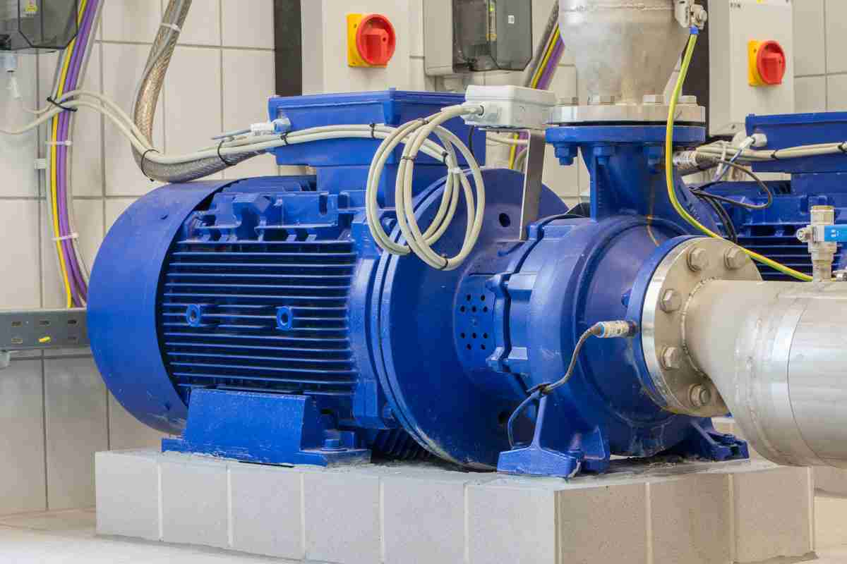
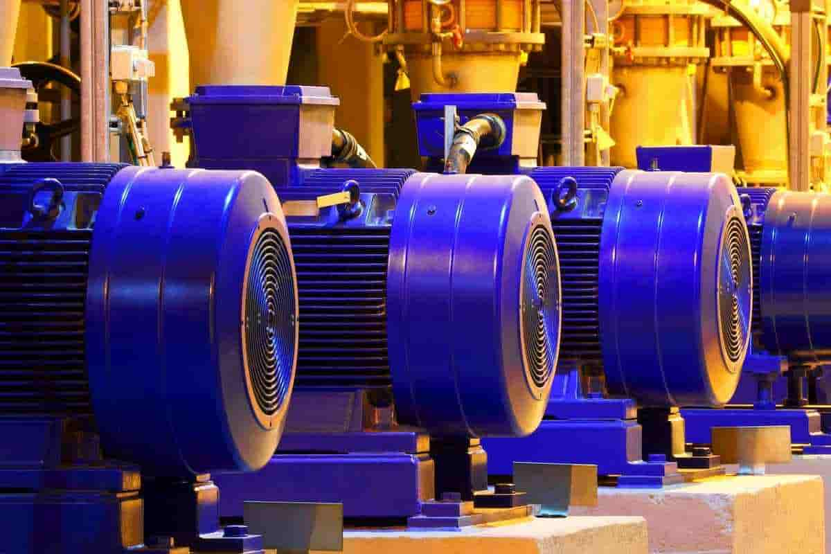
Buy all kinds of centrifugal pump parts + price
How does a 0.75 HP centrifugal pump parts work? The majority of centrifugal pumps share a few parts in common.
centrifugal pump parts name
These components consist of:
- Impeller
- House in the spreader or propeller style
- Axis
- Sleeved shafts
- Bearing A ball
- Setting up a seal
 The liquid end and the mechanical end of these components can be distinguished.
The wet end of the pump includes those sections that govern the hydraulic performance of the pump.
The components of the mechanical end allow rotation, which is how the fluid end generates flow and pressure, support the impeller inside the housing, seal the housing through which the shaft passes, and allow for these functions.
It tends
The casing and the impeller, the two major components of a pump, have already been covered. So, we won't go into great detail about them here.
The water is given speed by the impeller's rapid rotation, which is the brief explanation. The housing, which the impeller is installed inside of, is what transforms the impeller's rotational speed into pressure. See this article for a more thorough examination.
End mechanical
The pump's mechanical c
omponent consists of the shaft sleeve, bearings, sealing mechanism, and pump shaft.
Motor shaft
The shaft on which the impeller is installed. The shaft is typically sized to support the impeller and is composed of steel or stainless steel. Pivots require precise planning.
A short shaft may cause the pump to vibrate more, have a shorter bearing life, have a higher chance of breaking, and have a lower total pump life. A larger shaft, however, can unnecessarily drive up the price of the pump.
Blade sleeve
In the majority of pumps, a shaft sleeve protects the portion of the shaft that is below the seal. A shaft sleeve is a metal sleeve that slides over the shaft. It is often made of bronze or stainless steel. The shaft sleeve is used to protect the shaft as well as to position the impeller correctly on it.
Setting up a seal
The stuffing box refers to the location where the shaft passes through the housing. The space between the shaft and the box wall needs to be sealed using a sealing device. This area can be sealed using packing or mechanical sealing.
The liquid end and the mechanical end of these components can be distinguished.
The wet end of the pump includes those sections that govern the hydraulic performance of the pump.
The components of the mechanical end allow rotation, which is how the fluid end generates flow and pressure, support the impeller inside the housing, seal the housing through which the shaft passes, and allow for these functions.
It tends
The casing and the impeller, the two major components of a pump, have already been covered. So, we won't go into great detail about them here.
The water is given speed by the impeller's rapid rotation, which is the brief explanation. The housing, which the impeller is installed inside of, is what transforms the impeller's rotational speed into pressure. See this article for a more thorough examination.
End mechanical
The pump's mechanical c
omponent consists of the shaft sleeve, bearings, sealing mechanism, and pump shaft.
Motor shaft
The shaft on which the impeller is installed. The shaft is typically sized to support the impeller and is composed of steel or stainless steel. Pivots require precise planning.
A short shaft may cause the pump to vibrate more, have a shorter bearing life, have a higher chance of breaking, and have a lower total pump life. A larger shaft, however, can unnecessarily drive up the price of the pump.
Blade sleeve
In the majority of pumps, a shaft sleeve protects the portion of the shaft that is below the seal. A shaft sleeve is a metal sleeve that slides over the shaft. It is often made of bronze or stainless steel. The shaft sleeve is used to protect the shaft as well as to position the impeller correctly on it.
Setting up a seal
The stuffing box refers to the location where the shaft passes through the housing. The space between the shaft and the box wall needs to be sealed using a sealing device. This area can be sealed using packing or mechanical sealing.
centrifugal pump parts assembly
How do mechanical seals function?
The cost, performance, and design of mechanical seals vary. One fixed face, one rotating face, a gland, and a spring make up the simplest seal.
The gland screws into the face of the stuffing box directly into the pump housing after fitting around the pump shaft.
The gland seals to the fixed sealing ring, also known as the mating ring, and secures it around the pump shaft.
The revolving sealing ring, also known as the primary ring, is forced up against the fixed mating ring by the spring and is sealed to the shaft by an elastomeric component.
The spring squeezes against a catch or retaining collar fastened to the pump shaft to exert pressure on the revolving main ring.
The only route for fluid to seep out of the stuffing box is to flow between the rings that are forced together by the spring because the revolving primary ring and the stationary primary ring are sealed to the gland and the shaft, respectively.
The spinning face rotates against the stationary surface while the pump shaft rotates. A tiny quantity of the pumped liquid passes through the surfaces, but due to the heat produced by the rotating sealing surfaces, it evaporates.
This little bit of liquid is sufficient to lubricate and cool the sealing surface.
The sealing surfaces will stop practically all leaks between the shaft and the box wall as long as they are kept clean, smooth, and lubricated.
Pump sleeve
The bearing assembly is the final component of the mechanical end. Centrifugal pumps often include anti-friction ball bearings as standard equipment. The same bearings, which are lubricated with grease or oil, are used in everything from electric motors to sliders to automobiles.
The bearings that support and secure the pump shaft must be sized to offer a suitable service life and be able to handle all the loads generated by the rotation of the impeller.
Design engineers and end users are frequently particularly interested in the minutiae of bearing arrangement design because bearing failures are one of the most frequent causes of pump downtime.
Pump specialists have a right to take the time to become knowledgeable about the pump bearing systems they work with.
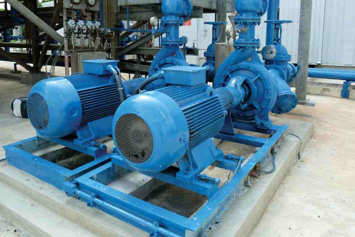
How Centrifugal Pump Work
How does a centrifugal pump work? A centrifugal pump is a mechanical tool used to transfer rotational energy from one or more impellers, or spinning rotors, in order to transport fluid.
The liquid enters the impeller, which rotates quickly around its axis before being ejected by centrifugal force through the impeller blade tips. The impeller's movement accelerates and presses the liquid while simultaneously steering it in the direction of the pump output.
The impeller directs the compressed liquid from the pump input to the pump casing, where it is then slowed and controlled before being discharged.
How do centrifugal pumps function?
The centrifugal pump's impeller is its most important part. It is made up of a number of curving fins.
Typically, these are sandwiched between two discs (closed impeller). An open or semi-open impeller (supported by a single disc) is preferred for fluids containing entrained solids.
The impeller's axis ("the eye") serves as the entrance point for liquid, which exits along the blades' perimeter.
The impeller, which is located on the other side of the eye, is connected to the motor via a drive shaft and rotates quickly (typically 500-5000 rpm). The liquid is accelerated through the impeller blades and into the pump casing by the rotating action of the impeller.
Volute and distributor are the two types of pump casings that are most common. To convert the fluid flow into a regulated discharge under pressure is the aim of both designs.
The impeller is deflected in a spiral casing, essentially forming a curved funnel with a growing cross-sectional area as it approaches the pump outlet. The fluid pressure rises toward the outlet as a result of this design.
For diffuser designs, the same fundamental idea holds true. As the fluid is ejected between a series of static vanes around the impeller in this instance, the fluid pressure rises.
Diffuser designs are more effective since they may be customized for certain uses. Velot cases work well in situations where moving highly viscous materials or liquids is advantageous since it prevents additional diffuser vane draughts.
The asymmetry of the coil design may cause the drive shaft and impeller to wear out more quickly.
What are a centrifugal pump's primary characteristics?
Positive displacement pumps and centrifugal pumps are the two primary categories of pumps. Centrifugal pumps, in contrast to the latter, are typically recommended for larger flows and for pumping liquids with a lower viscosity, up to 0.1 cP.
Centrifugal pumps may make up 90% of the pumps used in some chemical facilities. However, positive displacement pumps are favored for a number of applications.
centrifugal pump parts diagram
What are a centrifugal pump's limitations?
A centrifugal pump's impeller must rotate at a high speed continuously in order to function effectively. Centrifugal pumps lose efficiency with high viscosity inputs because there is greater resistance and more pressure is needed to maintain a certain flow rate.
Centrifugal pumps can generally be used to pump liquids with viscosities between 0.1 and 200 cP at low pressures and high capacities.
High viscosity oils or sludge can cause excessive wear and overheating, which can result in damage and early failure. Positive displacement pumps are less prone to these issues and frequently run at substantially lower speeds.
The high-speed impeller of a centrifugal pump has the potential to harm any pumped medium that is sensitive to shear (separation of solutions, biological fluids, or emulsions, for example). In these circumstances, a positive displacement pump's slower speed is ideal.
Another drawback is that, unlike a positive displacement pump, a centrifugal pump requires filling with the pumped liquid before it can create suction.
Because of this, intermittent supply applications are inappropriate for centrifugal pumps. Furthermore, a centrifugal pump generates a variable flow if the supply pressure changes.
A positive displacement pump will operate consistently and is insensitive to changes in pressure. A positive displacement pump is therefore preferred in applications where accurate dosing is needed.
What are some of the primary uses for centrifugal pumps?
In industrial, agricultural, and home applications, centrifugal pumps are frequently used to pump water, solvents, organics, oils, acids, bases, and any "thin" liquid.
In reality, there is a centrifugal pump design that works well in practically every situation when low viscosity fluids are involved.
Summary
One or more rotating rotors, known as impellers, which are in motion, transfer rotational energy to operate a centrifugal pump.
The pump outlet is reached by the fluid travelling at a higher speed and pressure thanks to the impeller's operation. The centrifugal pump's straightforward design makes it simple to use, comprehend, and maintain.
For the majority of low-pressure, high-capacity pumping applications involving low-viscosity fluids like water, solvents, chemicals, and light oils, centrifugal pump designs provide straightforward, affordable solutions.
Water supply and flow, irrigation, and chemical transport in petrochemical factories are examples of typical applications.
Positive displacement pumps are used for applications that demand precision dosing, high pressures, and complicated feeds like emulsions, food, or biological fluids, and high viscosity fluids like thick and viscous oils.
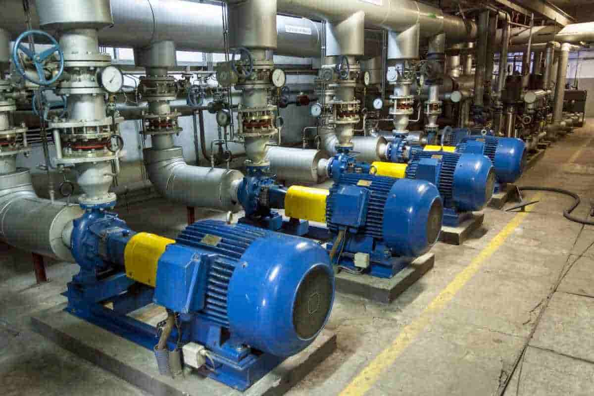
Centrifugal Pump Parts
What constitutes a centrifugal pump primary parts?
Rotor. A rotor used to boost the flow's kinetic energy is called an impeller.
Shell (volute). The casing serves as a pressure-limiting mechanism, containing the liquid and directing the flow of liquid to and from the centrifugal pump.
Shaft (rotor). The shaft on which the impeller is installed. The shaft is a mechanical part that transmits engine torque to the impeller.
Shaft gasket. O-rings or a mechanical seal, which are included with centrifugal pumps, aid to stop the leaking of the liquid being pushed.
Round bearing. Bearings reduce friction between the rotating shaft and the stator and restrict relative movement of the shaft (rotor).
Central components of a centrifugal pump
Each centrifugal pump has hundreds of individual components. The majority of centrifugal pumps share a few parts in common. The liquid end and the mechanical end of these components can be separated.
The components that affect the pump's hydraulic performance are found at the wet end. The impeller and the casing are the two primary wetted endpoints. The first radial bearing may occasionally be water lubricated. The bearing may also relate to wet edges in this situation.
The components that hold the impeller inside the casing are part of the mechanical end. The pump shaft, seal, bearings, and shaft sleeve are all parts of the mechanical portion of the pump.
These parts' functions are predetermined by their design:
Impeller and distributor for impellers. A rotor used to boost the flow's kinetic energy is called an impeller.
Shell (volute). The casing serves as a pressure-limiting mechanism, containing the liquid and directing the flow of liquid to and from the centrifugal pump.
The spiral is a bent funnel whose area grows as it gets closer to the discharge outlet. A centrifugal pump's volute is the casing that collects the fluid that the impeller pumps and reduces the liquid flow rate.
Thus, in accordance with Bernoulli's principle, the spiral increases pressure while lowering velocity to transform kinetic energy into pressure. Diffusers can be found in several centrifugal pumps.
A diffuser is an impeller-encircling group of fixed fins. The diffuser controls the flow, enabling a more progressive expansion and so raising the centrifugal pump's efficiency.
Shaft (rotor). The shaft on which the impeller is installed. The shaft is a mechanical part that transmits engine torque to the impeller.
Shaft gasket. O-rings or a mechanical seal, which are included with centrifugal pumps, aid to stop the leaking of the liquid being pushed.
Round bearing. Bearings reduce friction between the rotating shaft and the stator and restrict relative movement of the shaft (rotor). There are at least 5 typical bearing types, each of which operates in accordance with a different set of principles:
- Simple bearing
- Bearing for rolling elements
- Jewel
- Dynamic bearing
- Bearing a magnet
centrifugal pump impeller
Types of centrifugal pumps' impellers
The performance of a centrifugal pump is most significantly impacted by the design of the open, semi-open, and closed impeller. A well-designed impeller boosts efficiency, improves flow, and reduces turbulence.
A centrifugal pump's impeller might be one of three basic types:
Activate the impeller. The blades are unobstructed on all sides of an open propeller. Open impellers have a fragile structural design. They are typically utilized in low-cost pumps with tiny diameters and pumps for handling suspended particles.
Half-open impeller. On one side, the flaps are open, and on the other, they are closed. Shroud increases mechanical toughness. Additionally, they are more efficient than open impellers.
They can be utilized with liquids that have a minor amount of suspended particulates and in pumps with a medium diameter. It is crucial to keep the space between the impeller blades and the casing as narrow as possible in order to reduce circulation and other losses.
The impeller is shut. Between the two discs, the fins are cast as one piece. They are utilized in big, highly effective pumps with negligible net positive suction heads. The most popular pumps for handling transparent liquids are centrifugal pumps with closed impellers.
They rely on evenly spaced wear rings on the pump casing and impeller. Due to the impeller, a closed impeller is a more intricate and expensive design, although additional wear rings are required.
Blades for impellers include:
Blades are curved backwards (preferred design due to the negative slope of the performance curve)
Blades that are radial
Blades that are bent forward (due to positive slope conditions, this design may cause pump surges)
Impellers include
A vacuum. Liquid can enter the center of a single suction impeller's blades only from that direction.
Two suctions. Fluid can enter the center of the impeller blades from both sides simultaneously using a twin suction impeller. As a result, the shaft is subject to less force.
Depending on the design chosen, output pressure varies slightly. Both open and closed blades are possible. Additionally, fixed fins can be added to the diffuser to help direct the flow to the output.
The velocity at the impeller's tip correlates to the energy that is transmitted to the fluid. The speed head will increase as the impeller spins more quickly or becomes larger.
In general, the way fluid flows through centrifugal pumps can be used to classify them. This classification is based on the pump casing and impeller design rather than just the impeller itself. The following three flow types can go via a centrifugal pump:
- Circular flow
- Blended flow (part radial, part axial)
- Axial motion (propeller type)
How useful is this article to you?
Average Score
5
/
Number of votes:
1