If you like to know the differences between axial flow vs radial turbine water pumps, keep reading this article. While some centrifugal pumps use an impeller-style arc pump impeller, a centrifugal pump's impeller resembles a fan. Axial flow pumps pump fluid to the other side of the pump by pulling on the shaft and utilizing an impeller. The liquid is sucked up by the positive displacement pump. Axial Flow: Water flows perpendicular to the axis of the turbine. Example: Kaplan turbine, Girard, and Jonval. Mixed flow: Water exits in an axial direction and travels radially from the outer circumference. Modern Francis turbine, for instance. 3. Axial flow: The fluid is discharged along the spindle axis via an axial flow impeller. Axial flow pumps do not, therefore, operate in a "centrifugal" manner. Radial flow: The fluid is discharged 90 degrees radially from the spindle axis by the radial flow impeller. Type of pump Dynamic pump. Dynamic pumps exist in a variety of forms, some of which are mentioned below. These forms include centrifugal, vertical, horizontal, submersible, and fire hydrant systems. Centrifugal pump is one. The most popular kind of pump worldwide is this one. What distinguishes axial flow pumps from centrifugal pumps? 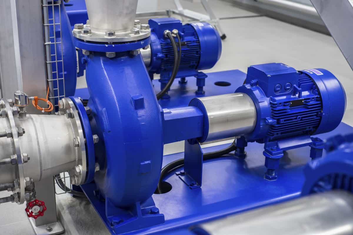 The fluid in an axial flow pump moves parallel to the axis of rotation. An axial impeller is located in the pipe of this type of dynamic pump. Axial flow pumps draw the liquid parallel to the axis of the impeller, whereas centrifugal pumps draw the liquid perpendicular to the impeller. What distinguishes a mixed flow turbine from an axial flow turbine? The multiphase turbine Water flows axially out of the impeller and radially in. For instance, the fluid flow is the axis of the turbine outlet in the most recent Francis waterwheel axial turbine. What distinguishes axial flow from radial flow? Axial Flow: The fluid is discharged along the spindle axis by the axial flow impeller. Axial flow pumps do not, therefore, operate in a "centrifugal" manner. Radial flow: The fluid is discharged 90 degrees radially from the spindle axis by the radial flow impeller. Which kind of power pump is that? According to the working fluid flow, dynamic pumps can be divided into two primary categories. Axial pumps have fluid suction flow parallel to the axis of the impeller, while centrifugal pumps have fluid suction flow perpendicular to the impeller. We discussed centrifugal pumps in our earlier article.
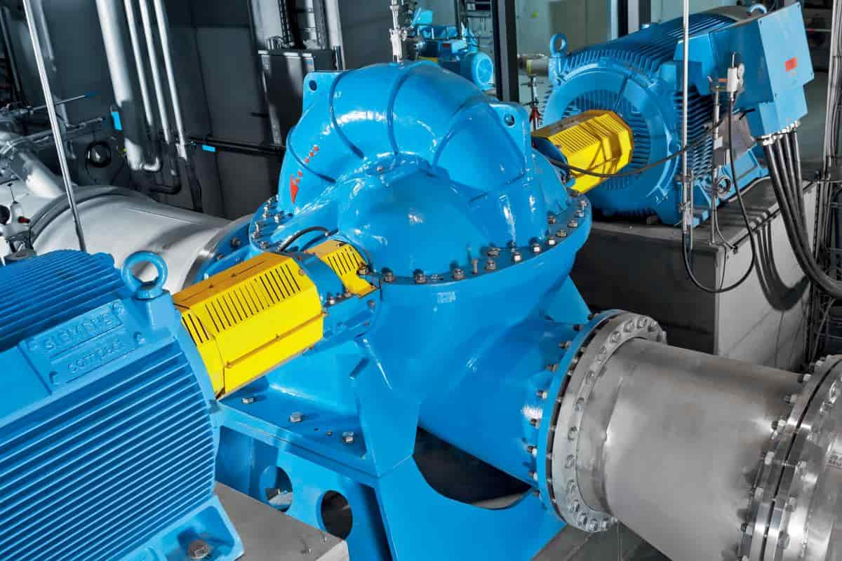
Axial Flow Water Pumps
A popular kind of water pump called an axial flow pump, or AFP, is primarily made up of an impeller in a pipe. A sealed engine installed inside the pipe, an electric motor mounted outside the pipe, a gasoline or diesel engine, or a vertical drive shaft that enters the pipe can all be used to turn the screw. Because the difference in radius at the pump's inlet (also known as "suction") and output (also known as "discharge") is so minimal, the fluid particles do not change their radial location as they pass through the pump. Thus, "axial" pump is named. A screw-type impeller of an axial flow pump is housed in a casing. Fluid flowing through the impeller's vanes in an axial flow pump develops pressure in the device. In other words, the fluid particles do not change their radial location as they flow through the pump since the fluid is pushed in a direction parallel to the shaft of the impeller. It enables fluid to flow almost axially out of the wheel and axially into it. An axial flow pump's screw is propelled by a motor. The figure depicts the axial flow pump's features. The head at zero flow rate, as depicted in the image, can be up to three times higher than the head at the pump's peak efficiency. Additionally, the power need increases with decreasing flow since the maximum amount of power is drawn at zero flow. This characteristic differs from the radial flow centrifugal pump, in which the power consumption rises as the flow increases. Additionally, as altitude rises, power requirements and pump height rise as well. This allows the pump to be adjusted to system circumstances for the most effective functioning.
- Professionals
The fundamental benefit of an axial flow pump is that it has a reasonably high discharge and low head (vertical distance) (flow rate).  For instance, compared to the more typical radial flow or centrifugal pumps, it may pump up to three times as much water and other liquids in elevators under four meters. By adjusting the screw pitch, it is also easily adaptable to work as efficiently as possible at low flow/high pressure and high flow/low pressure. The length of the impeller blades and the impact of turning the fluid in an axial pump are both quite little. Lower hydrodynamic losses and improved levels of efficiency are the effects of this. These pumps are more appropriate for lower elevations and higher discharges and have the smallest dimensions of many traditional pumps.
- Apps
AFPs are also utilized in the transfer pumps that sailboats use for ballast. They are employed in power plants to pump water from a lake, river, reservoir, or the ocean to cool the main condenser. They are utilized in the chemical sector, such as evaporators and crystallizers, to disperse vast volumes of liquids. AFPs are frequently used in wastewater treatment to internally recirculate mixed fluids. Very powerful AFP engines are employed in the marine and agricultural sectors to lift water for drainage and irrigation. In East Asia, there are millions of cars with less power (6–20 horsepower), the majority of which are single-cylinder diesel and gasoline engines. Small farmers use them for drainage, fishing, and irrigation. The wheels' design has been enhanced, increasing efficiency and lowering the energy expenses associated with farming there. Since they can now be 6 meters or longer (frequently employed walking tractors), they can more safely "compromise" the water supply at the same time as the power source. Additionally, they are stored in safer and more durable locations. 
Radial Flow Turbine Water Pumps
A turbine with radial flow is one in which the working fluid moves radially in relation to the shaft. The primary distinction between axial and radial turbines as a result of the direction of fluid flow through the parts is therefore this. In rotary shaft turbines, the flow of the fluid "actuates" the rotor, while in radial turbines, the flow is smoothly directed perpendicular to the axis of rotation, and when a water mill is running, water drives the turbine. As a result, radial turbines are easier to construct, more robust, and more efficient (with the same power range) than axial turbines. This results in reduced mechanical and thermal stress (particularly where the working fluid is hot). Radial turbines, on the other hand, are no longer cost-competitive for big power ranges (greater than 5 MW) and their efficiency is the same as axial turbines. This is because of heavy and expensive rotors. The creation of radial flow turbines dates back more than 180 years, when they were first created to produce hydraulic power. The Francis turbine is an illustration of a radial inflow turbine. The flow path in this machine is one that moves from the radial to the axial direction. For single-stage turbines, flow fluctuation in the opposite direction (radial exit) causes a number of issues. Low selectivity of employment is one of these issues.  Multi-stage radial steam turbines, however, are already widely used throughout Europe. For instance, the Ljungström steam turbine significantly increases the specific volume of steam, which nearly always necessitates the use of the radial outlet flow channel.
- Hydraulic radial turbines
The fluid essentially flows in a plane perpendicular to the axis of rotation in radial flow fluid turbines. Axial and radial flow turbines are two types of reactive fluid turbines. For pressure loads from 600 m to 30 m, Francis turbines, for instance, are reaction turbines. The flow enters the turbine wheel radially and departs axially in such flow units. Water can flow radially in radial flow reaction turbines from the inside out (inward radial flow turbine) or from the outside in (outward radial flow turbine).
- Turbines with Radial Outlets
Radial output turbines were the first hydraulic turbines. These conventional turbines include Hero's turbine. The turbine on the Hero serves as a sprinkler to water the grass. The first successful commercial radial hydraulic turbine was created by French engineer Fourneyron. In these turbines, water enters the turbine wheel's center and exits through the wheel. The actuator is surrounded by a slide. The impeller of the turbine outflow reaction's inlet is its inner diameter, and its exit is its outer diameter. 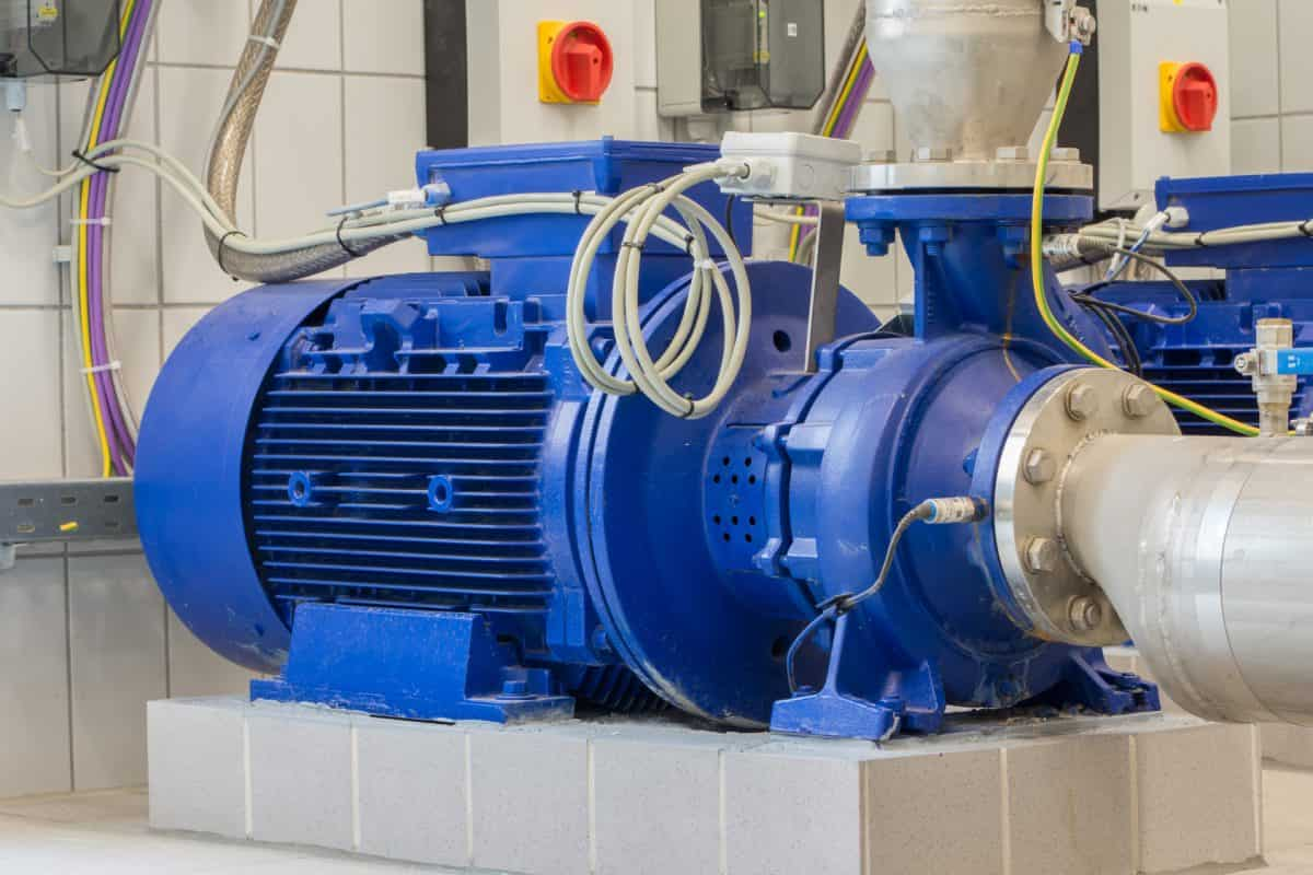
- Inlet Radial Turbine
The radial intake hydraulic turbine made its debut as a power generation operational unit in the hydraulic turbine area. The Francis turbine is the most popular type of water turbine. Radial and axial flow are combined in Francis, an inflow reaction turbine. The power output, mass flow rate, and rotational speed of the input radial turbine are all highly variable. It can be utilized in large hydroelectric power plants that can generate hundreds of megawatts of power and small enclosed gas turbines that can generate a few kilowatts. The most popular water turbines in use today are Francis turbines. They generate power primarily and operate between 10 and 650 meters high. Excluding microfluidics, power varies from 10 to 750 MW. To keep the water flowing, it requires a cover. The turbine is typically situated between the low-pressure water discharge pipe and the high-pressure water reservoir at the base of a dam. The entrance has a helical design. Water is directed toward the turbine wheel via the vanes. The runner rotates as a result of the radial flow's impact on the runner blades. The wicket can be changed to enable the turbine to function well in a variety of water flow scenarios. The runner's diameter ranges from 1 to 10 meters. Between 83 and 1,000 rotations per minute are made by the turbine. Large and medium Francis turbine shafts are often constructed vertically. Small turbines can also be arranged vertically, however they typically have a horizontal shaft.
- Components of a radial flow hydraulic turbine
The key parts of the radial water turbine are listed below. 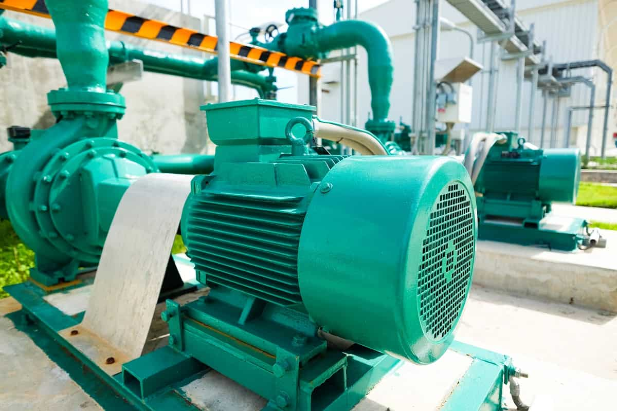
- Encase
The cage of a radioactive water turbine is always filled with water. The penstock allows moisture to penetrate the cap. In a radial flow hydraulic turbine, the turbine wheel is entirely encased. A radial flow turbine's casing is spiral-shaped to ensure that water enters the raceway at an even velocity all the way around. The case's cross-sectional area steadily shrinks. Concrete, cast steel, or sheet steel are used to make the body. The tiles of Stay Vanes Station are secured. Due to radial flow, as water enters the blades, they lessen the swirl of water. They increase the turbine's efficiency as a result.
- Vanes
Around the turbine wheel, the blades are essentially mounted on a fixed impeller. The guides make sure that there is no collision when the water enters the turbine wheel at the intake. Guidewires are dynamic, unlike graded institutions. A device to alter the volume of water striking the blades can be used to change the actuator's breadth between two adjacent blades. They also ensure that water strikes turbine blades at the proper angle to maximize efficiency. In light of the load on the turbine, the control pins enable greater control of turbine performance.
- Runner
A set of radial blades are fitted on a circular impeller that makes up the impeller of a radial flow hydraulic turbine. To reduce fluid loss, the surface of these sheets has been polished. Water may enter and exit the runner without hitting anything because to the curved blades' design. The spindle secures the runner. Cast steel, cast iron, and stainless steel are available as concrete runner materials.
- Pipe in draught
Typically, air pressure is not present at the turbine wheel's radial flow output. As a result, the water at the outlet cannot be discharged directly into the trunk.  The water is therefore discharged from the turbine wheel exit to the tail using a pipe or tube with a larger cross-sectional area. A draught tube is a pipe or tube like this.
- Rotating gas turbines
Modern compact gas turbines have numerous moving parts, bearings, seals, lubrication systems, and sophisticated electronic controls, making them technically difficult machines. Durability is typically compromised for efficiency in most gas turbine designs because they are frequently not portable and cannot withstand extreme climatic conditions. While most major power generation projects would benefit from this, it is not appropriate for tiny, portable power generation. Radial turbines can run at comparatively greater pressure ratios in each stage with lower flow rates than axial flow turbines. These engines' specific speed and power are therefore in the lower ranges. For high temperature applications, cooling the rotor blade in radial stages is more difficult than in axial turbine stages. Even in non-design settings, variable-angle nozzle blades in the radial turbine stage offer improved stage efficiency. Without diverting the axial flow, the single disc radial gas turbine runs on a straight radial flow system. There are only two key parts to this design: a revolving disc with a high current discharge turbine and a centrifugal compressor attached to a generator (and starter) The fuel lines attached to the stator shroud and leading directly to the burner, as well as the stator shroud containing the burner and nozzles. Due to aerodynamic losses in the stage, the stage generation is lower than the isentropic enthalpy function. The work performed by the stage less the friction and losses from the rotating discs results in the actual power on the turbine shaft.