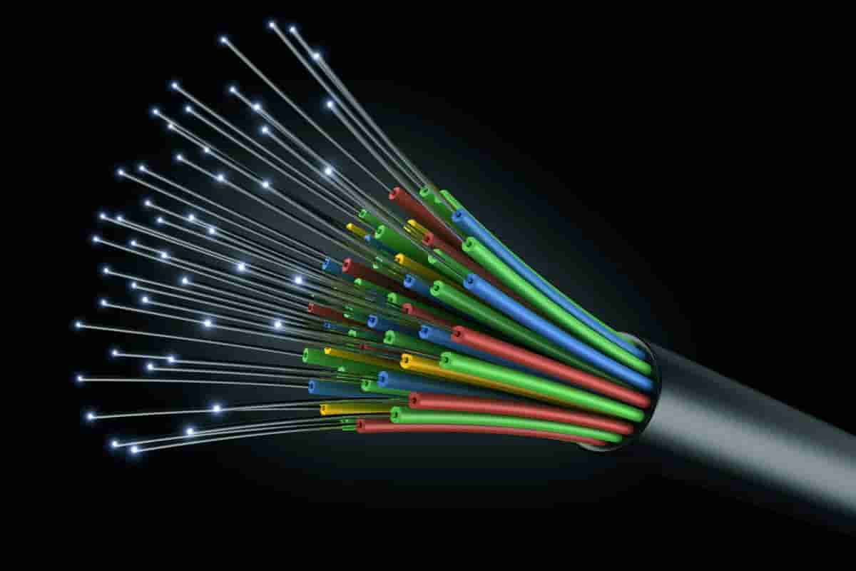
Science made our life easier in every aspect where human beings never dreamed and defined new definition for communication. Optic fibre or optical fiber is one of the latest advancements where it shines in terms of speed.
fiber optic cable
A single, microscopic filament that is drawn from molten silica glass is what makes up an optical fiber. In high-speed and high-capacity communications systems that convert information into light, which is then transmitted via fiber optic cable, these fibers are gradually replacing metal wire as the transmission medium. Fiber optic cables are most commonly used by American telephone companies at the moment; however, the technology is also implemented in power lines, local access computer networks, and the transmission of videos. Around the year 1880, American inventor Alexander Graham Bell made his first attempt to communicate using light. Bell is most well-known for his role in developing the telephone. However, it wasn't until the middle of the 20th century that light wave communication became a real possibility. At that time, technological advancements made it possible to create a transmission source (the laser) and an effective medium (the optical fiber). After the invention of the laser in 1960, scientists in England found that silica glass fibers could carry light waves without significant attenuation, or loss of signal. This discovery was made six years after the invention of the laser. In 1970, a new kind of laser was invented, and that same year marked the beginning of commercial production of optical fibers. Optical fiber cables are used to connect the datalinks that make up a fiber optic communications system. These datalinks typically contain lasers and light detectors. A datalink is a device that transforms analog electronic signals, such as those produced by a telephone conversation or the output of a video camera, into digital pulses of laser light in order to facilitate the transmission of information. These are then transmitted along the optical fiber to another datalink, where they are detected by a light detector and converted back into an electronic signal. The Basic Components Although silicon dioxide (SiO 2) makes up the majority of an optical fiber's make-up, trace amounts of a variety of other chemicals are frequently included. 
fiber optic cable internet
In the now-defunct crucible manufacturing method, highly purified silica powder was used. In contrast, the primary source of silicon for the vapor deposition method, which is currently in widespread use, is liquid silicon tetrachloride (SiCl 4) in a gaseous stream of pure oxygen (02). In order to produce core fibers and outer shells, also known as claddings, with function-specific optical properties, other chemical compounds such as germanium tetrachloride (GeCl 4) and phosphorus oxychloride (POC1 3) can be used. Because the purity of the glass used in optical fibers and its chemical composition determine the degree of attenuation, which is the most important characteristic of a fiber, current research is focused on developing glasses with the highest possible purity. Because they are transparent to nearly all of the visible light frequency range, glasses with a high fluoride content hold the most promise for increasing the performance of optical fibers. This is because fluoride is a component of fluorine. Because of this, they are particularly useful for multimode optical fibers, which are capable of transmitting hundreds of separate light wave signals concurrently. For the purpose of providing support, a fiber optic cable is constructed with a core that is made of either a steel cable or a high-strength plastic carrier. Around this core are wrapped numerous individual optical fibers. After that, layers of protective materials like as aluminum, Kevlar, and polyethylene are applied over this core (the cladding). Light moves between the core and the cladding at somewhat different speeds due to the fact that they are made of slightly different materials. When a light wave that is moving through the fiber core hits the boundary between the core and the cladding, the light wave is bent back into the core because of the compositional variations between the core and the cladding. As a result, a light pulse that is traveling through an optical fiber is constantly being reflected away from the cladding as it moves along. A pulse travels through an optical fiber at the speed of light, which is 186,290 miles per second (299,340 kilometers per second) in a vacuum but is slightly slower in practice. As the pulse travels through the optical fiber, it only loses energy due to impurities in the glass and the energy absorption that occurs due to irregularities in the structure of the glass. The amount of energy that is lost through attenuation in an optical fiber is quantified in terms of the loss (in decibels, which is a unit of energy) that occurs per unit of distance traveled by the fiber. After a certain distance, the signal becomes faint and either needs to be amplified or it must be repeated. 
fiber optic cable price
The typical loss rate for an optical fiber is 0.2 decibels per kilometer, which means that this loss rate is quite low. With the datalink technology that is available today, it is essential to install laser signal repeaters around every 30 kilometers (18.5 miles) along a long-distance cable. In spite of this, ongoing investigations into the purity of optical materials are being conducted with the goal of increasing the distance between repeaters of an optical fiber to one hundred kilometers (62 miles). Optical fibers can be divided into two distinct categories. When compared to the diameter of the cladding, the core of a single-mode fiber is typically much smaller, measuring only 10 micrometers (one micrometer is equal to one millionth of a meter), while the cladding measures 100 micrometers. When only one light wave needs to be sent over a significant distance, a single-mode fiber is the best option. Both submarine cables and long-distance telephone lines use bundles of single-mode optical fibers to transmit data and voice signals. Multimode optical fibers, which have a core diameter of 50 micrometers and a cladding diameter of 125 micrometers, are able to transport hundreds of distinct light wave signals over shorter lengths than single-mode optical fibers. In urban systems, where a large number of signals need to be transported to central switching stations in order to be distributed, this type of fiber is utilized. The Procedures Involved in Production A highly purified kind of silica glass is used in the construction of an optical fiber's core as well as its cladding. One of two processes can be used to transform silicon dioxide into an optical fiber. The first technique, known as the crucible process and involving the melting of powdered silicon, results in the production of thicker multimode fibers that are suited for the transmission of many light wave signals over shorter distances. 
fiber optic cable near me
The second method, known as vapor deposition, involves the creation of a solid cylinder consisting of core and cladding material. This cylinder is then heated and pulled into a thinner, single-mode fiber that may be used for communication over long distances. Outer Vapor Phase Deposition, Vapor Phase Axial Deposition, and Modified Chemical Vapor Deposition are the three different types of processes that fall under the category of vapor deposition (MCVD). The MCVD process, which is now the most used method of manufacturing, will be the primary emphasis of this section. MCVD produces a fiber with a low loss that is ideal for use in cables that run for long distances. MCD1 stands for modified chemical vapor deposition. The first step in the process involves the creation of a cylindrical preform by depositing layers of silicon dioxide that has been carefully prepared on the inside surface of a hollow substrate rod. A gaseous stream of pure oxygen is directed toward the substrate rod in order to accomplish the deposition of the layers. A variety of chemical vapors, including silicon tetrachloride (SiCl 4), germanium tetrachloride (GeCl 4), and phosphorous oxychloride (POC1 3), are introduced to the stream of oxygen. These chemicals include germanium tetrachloride (GeCl 4) and phosphorous oxychloride (POC1 3). When oxygen comes into touch with the rod's hot surface, high-purity silicon dioxide is produced. This is made possible by a flame that burns beneath the rod and retains its walls at a very high temperature. The end result is a glassy soot that is produced inside the rod, and it is several layers deep. This soot will eventually turn into the core. The types of chemical vapors that are utilized can have a significant impact on the characteristics of these layers of soot. 2 After the soot has been layered to the desired depth, the substrate rod is moved through additional heating steps to remove any moisture and bubbles that have become trapped in the soot layers. While the boule or preform of highly pure silicon dioxide is being formed during the heating process, the substrate rod and the internal soot layers begin to solidify. 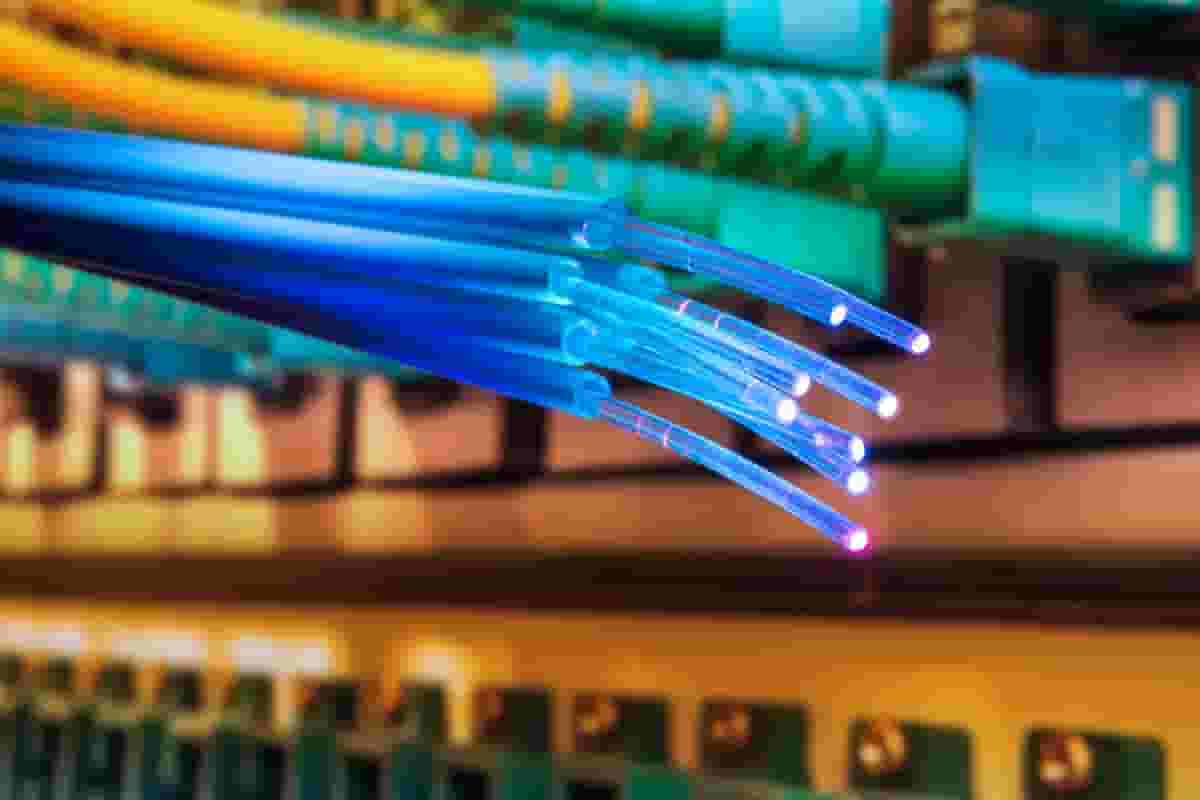
fiber optic cable types
A preform typically ranges in diameter from 10 millimeters to 25 millimeters (.39 inches to.98 inches) and length from 600 millimeters to 1000 millimeters (23.6 inches to 39.37 inches). Bringing the fibers together 3 After that, an automatic transfer takes place to a vertical fiber drawing system, which receives the solid preform. The machines that make up a typical vertical drawing system can be as high as two floors and have the capacity to produce continuous fibers that are as long as 186 miles (300 kilometers) in length. This system is comprised of a furnace that is used to melt the end of the preform, sensors that are used to measure the diameter of the fiber that is being extracted from the preform, and coating equipment that are used to apply protective layers over the outside cladding. 4 The preform is initially placed in a furnace, where it is heated to a temperature of around 3600 degrees Fahrenheit (about 2000 degrees Celsius). Next, a drop of molten glass that is called a "gob" forms at the end of the preform. This droplet of glass is analogous to the drop of water that gathers at the bottom of a leaking faucet. After that, the gob is removed, and the single optical fiber that was contained within the preform is extracted. The cladding of the optical fiber is formed from the material that was in the initial substrate rod, while the core of the optical fiber is formed from silicon dioxide that was deposited as soot during the process of pulling the optical fiber from the preform. 5 During the process of drawing out the fiber, one set of measuring devices monitors its diameter and its concentricity while another set of measuring devices applies a protective coating. After going through a curing furnace and another measurement apparatus that measures diameter, the fiber is then wound on a spool to be stored. Assurance of Quality The suppliers of the chemical compounds that are utilized as the raw materials for the substrate rods, chemical reactants, and fiber coatings are the first point of inspection in the quality control process. The thorough chemical analyses of the constituent chemicals are provided by specialty chemical suppliers, and the accuracy of these analyses is continually monitored by computerized on-stream analyzers that are attached to the process vessels. 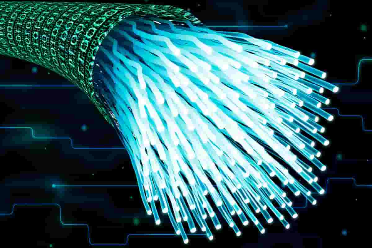
fiber optic cable light
During the process of creating preforms and drawing fibers, process engineers and highly skilled personnel keep a close eye on the vessels that are shut off. Computers are used to operate the intricate control systems that are required to successfully handle the high temperatures and pressures that are present during the production process. The diameter of the fiber is continuously monitored by precise measurement instruments, which also offer feedback for the purpose of controlling the drawing process. The Times to Come Ongoing research into materials that have superior optical characteristics will provide the foundation for the development of future optical fibers. At this time, silica glasses that contain a high percentage of fluoride show the most potential for use in optical fibers. These glasses have attenuation losses that are even lower than those of today's extremely efficient fibers. Earlier fibers typically had losses of 0.2 decibels per kilometer, but experimental fibers drawn from glass containing 50 to 60 percent zirconium fluoride (ZrF 4) now show losses in the range of 0.005 to 0.008 decibels per kilometer. This is a significant improvement over the previous fibers' losses. In addition to adopting materials of higher quality, manufacturers of fiber optic cables are currently experimenting with ways to improve production processes. At the moment, the most cutting-edge production procedures involve the utilization of high-energy lasers for the melting of the preforms that are used for the fiber draw. 
fiber optic christmas tree
Single-mode fibers with a length of between 1.2 and 15.5 miles can be drawn from a single preform at a rate of 10 to 20 meters (32.8 to 65.6 feet) per second. The length of the fibers that can be taken from a preform can range from 2 to 25 kilometers (1.2 to 15.5 miles). At least one business has stated that it has created fibers that are 160 kilometers (99 miles) in length, and the regularity with which fiber optics companies are currently retooling—as frequently as once every eighteen months—suggests that much more significant advancements are still to come. These developments will be driven in part by the rising usage of optical fibers in computer networks. They will also be driven in part by the increasing demand for the technology in emerging international markets such as Eastern Europe, South America, and the Far East. 